13
OTHER FUNCTIONS
13-16
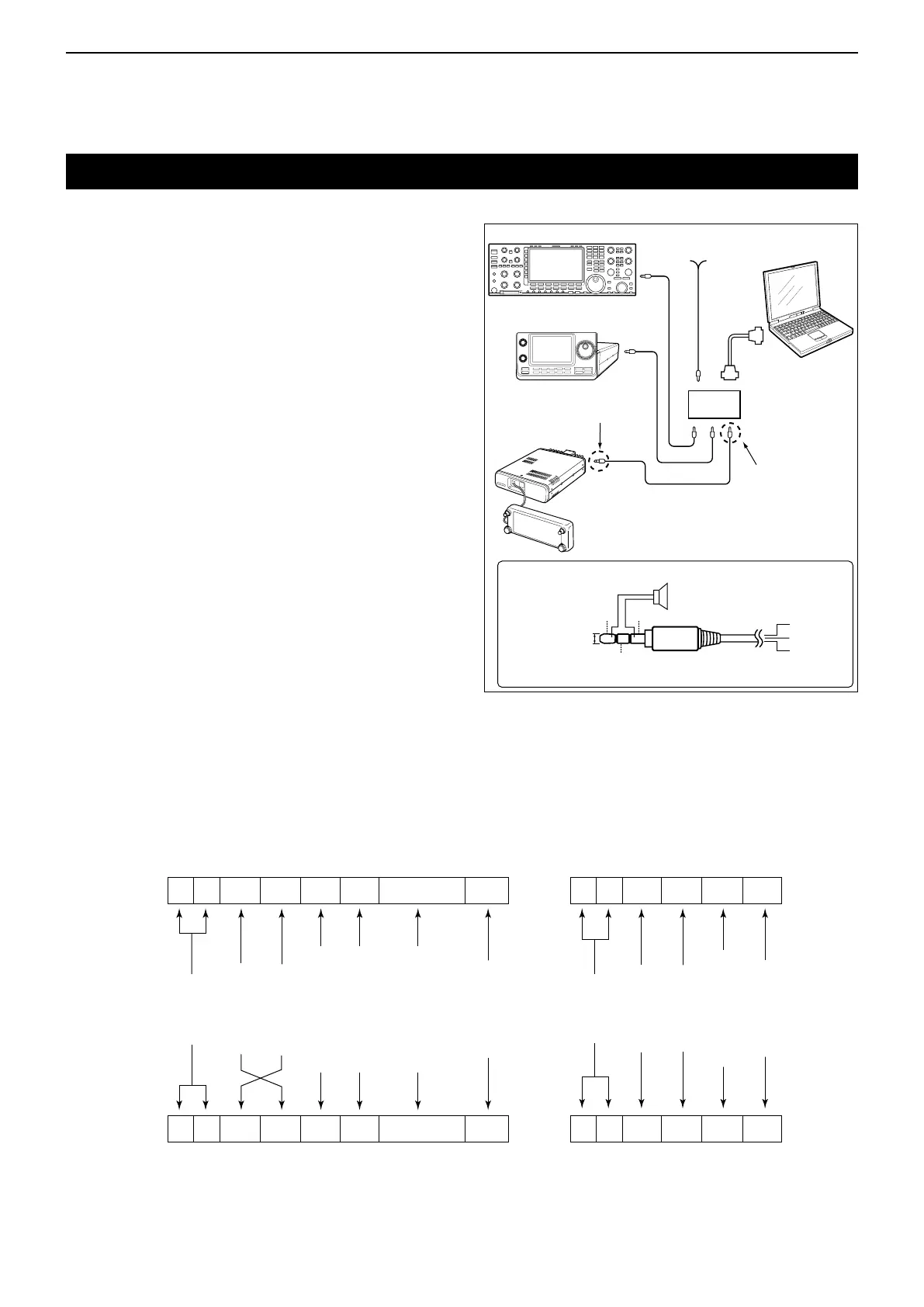
D CI-Vconnectionexample
The transceiver can be connected through an optional
CT-17 c i -v l e v e l c o n v e r t e r to a PC equipped with an
RS-232C port. The Icom Communications Interface-V
(CI-V) controls the transceiver.
Up to 4 Icom CI-V transceivers or receivers can be con-
nected to the PC. See page 12-56 for setting the CI-V
condition using the set mode.
Remotejack(CI-V)information
Controller to ID-5100A/E
FE FE 8C E0 Cn Sc Data area FD
Preamble
code (fixed)
Transceiver’s
default address
Controller’s
default address
Command number
(see the command table)
Sub command number
(see the command table)
BCD code data such as
for frequency, memory
number entry
(see the data content description)
End of message
code
(fixed)
OK message to controller
FE FE E0 8C FB FD
FE FE E0 8C FA FD
Preamble
code
(fixed)
Controller’s
default address
Transceiver’s
default address
OK code
(fixed)
End of message
code
(fixed)
NG message to controller
NG code
(fixed)
ID-5100A/E to controller
qwerty u
FE FE E0 8C Cn Sc Data area FD
qwerty u
CT-17
Power source
DC 9–15 V
RS-232C
cable
ID-5100
to [SP2]
PC
3 conductor
3.5 (d) mm plug
2 conductor
3.5 (d) mm plug
3.5 (d) mm
GND
I/O
SP
SP
GND
SP
I/O
• Connections (ID-5100A/E side)
*No speaker is necessary for the CT-17 side.
D Dataformat
The CI-V system uses the following data formats. Data
formats differ depending on command numbers. A data
area or sub command is added to some commands.

 Loading...


