190-01115-01 G3X/G3X Touch Installation Manual - GI 260 Installation
Rev. AC Page 11-2
11.3 General Specifications
See Section 2.2 for power/current specifications, and Section 2.4.1 for dimension/weight specifications.
11.4 Unit Installation
Fabrication of a wiring harness is required. Sound mechanical and electrical methods and practices are
recommended for installation of the GI 260. Refer to Section 2.3
for wiring considerations, and to
Section 25.6
for pinouts.
1. Select a mounting location where the GI 260 is easily visible, but does not impede the pilot’s field
of view, typically the glareshield.
2. If needed, make a hole in the glareshield to run the pigtail harness through.
3. Secure the Socket Mount to a suitable mounting location (glareshield) using (3) #6-32 100º flat
head screws.
4. Insert the GI 260 into the Socket Mount, adjust for best viewing angle.
5. Make connections (Figure 26-1.6
) to the pigtail harness by either splicing wires or adding a D-sub
connector to the end of the pigtail (after it has run through glareshield or mounting surface) and
connect to another D-sub connector on harness.
6. Shields should be continued through any splices by grounding your shield to the spare shield
ground drain wires.
7. If applicable, assemble the connector backshells and connect backshell connectors.
11.5 Unit Calibration
An in-flight AOA calibration is required for GI 260 installations, see Section 33.4.6.1 and Section 33.4.6.2
(for GDU 37X installations) or Section 34.4.7.1
and Section 34.4.7.2 (for GDU 4XX installations).
11.6 Unit Operation
See Figure 11-2 for AOA display descriptions.
The GI 260 has two buttons below the display labeled as TEST and MUTE. When the TEST button is
pressed, the GI 260 performs a self test. During the self test, all indicators on the display will be
illuminated to signal that the unit passes the test. The red chevrons on the display will flash on and off to
indicate a failure. Releasing the TEST button restores normal operation.
Pressing the MUTE button mutes any currently playing audio. The audio will then remain muted until any
Stall Warning (red) or Caution Alert (yellow) conditions have returned to a Minimum Visible (green)
condition. The mute operation is then reset, and audio is unmuted.
Figure 11-2 GI 260 Display
6.80 172.7
0.04 1
TYPICAL THICKNESS
BENEATH FASTENER HEAD
2X 6.40
162.6
2X 0.42
10.7
2.00 50.8
2X 0.20
5.1
3.4 86
CENTER OF GRAVITY
2.94 74.7
2.00 50.8
4.98 126.6
1.1 27
CENTER OF
GRAVITY
0.2 4
CENTER OF GRAVITY
NOTE:
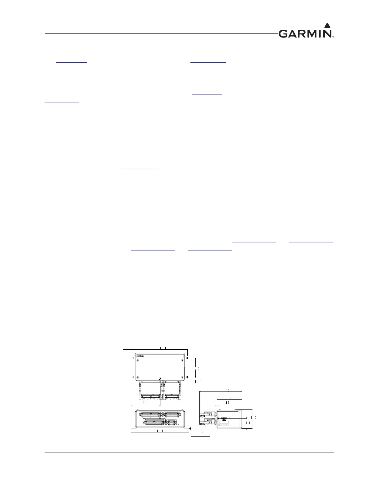
1. DIMENSION: INCHES[mm]. METRIC VALUES ARE
FOR REFERENCE ONLY.
2. DIMENSIONS ARE NOMINAL AND TOLERANCES
ARE NOT IMPLIED UNLESS SPECIFICALLY STATED

 Loading...