190-01115-01 G3X/G3X Touch Installation Manual - LRU Pinouts
Rev. AC Page 25-38
25.5.15 Shunt
Shunt Channel 2, has two inputs (either pin 34 & 35 of the J243 or pin 46 & 47 of the J244) for the single
channel. Use the inputs from one connector (J243 or J244) only.
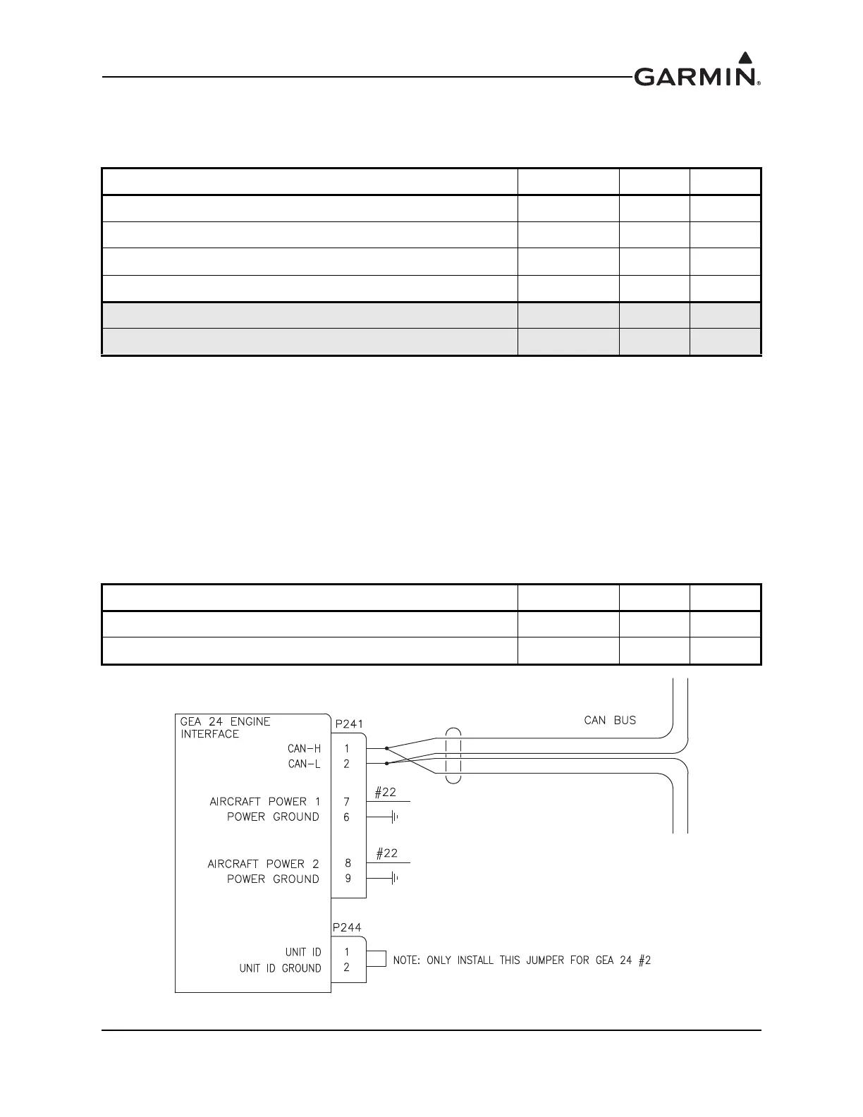
25.5.16 System ID
Pins 1 and 2 must be left open (floating) for a single GEA 24 installation. When using a GEA 24 and GSU
73 in the same system, pins 1 and 2 should be connected together in order to configure the GEA 24 as the
EIS #2 LRU. If two GEA 24s are installed, connect pins 1 and 2 on the second GEA 24 together in order to
configure it as the EIS #2 LRU.
When using two GEA 24 units to monitor a single engine with more than 6 cylinders, connect cylinders
1-6 to the CHT/EGT 1-6 inputs on GEA 24 #1, and cylinders 7-12 to the CHT/EGT 1-6 inputs on
GEA 24 #2.
When using two GEA 24 units to monitor twin engines (or a larger than normal single engine), connect
pins 1 and 2 on the second GEA 24 to configure it as the EIS #2 LRU.
Figure 25-16 GEA 24 EIS #2 Configuration
Pin Name Connector Pin I/O
SHUNT 1 HI J243 37 In
SHUNT 1 LO J243 36 In
SHUNT 2 HI* J243 35 In
SHUNT 2 LO* J243 34 In
SHUNT 2 HI* J244 46 In
SHUNT 2 LO* J244 47 In
Pin Name Connector Pin I/O
SYSTEM ID 1A J244 1 In
SYSTEM ID 1B / GND J244 2 --

 Loading...