190-01115-01 G3X/G3X Touch Installation Manual - GEA 24 Installation
Rev. AC Page 10-2
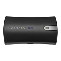
10.1.1 Status LED
The GEA 24 has an LED on its outer case that indicates its current status. See Section 35.1.1
for details.
10.2 Equipment Available
10.2.1 Required Equipment
10.2.2 Additional Equipment Required
Table 10-2 lists the content of the GEA 24 Connector Kit, which is required to install the unit. Use of the
CAN Termination Kit is detailed in Section 2.3.1.3.3
.
Table 10-1 GEA 24 Part Numbers
Model
Assembly Part
Number
Unit Only Part
Number
GEA 24 010-01042-00 011-02848-00
Table 10-2 Contents of GEA 24 Connector Kit (011-02886-00)
Item Garmin P/N Quantity
Backshell w/Hdw, Jackscrew, 9/15 Pin 011-01855-00 1
Backshell w/Hdw, Jackscrew, 25/44 Pin 011-01855-02 1
Backshell w/Hdw, Jackscrew, 37/62 Pin 011-01855-03 1
Backshell w/Hdw, Jackscrew, 50/78 Pin 011-01855-04 1
CAN termination kit 011-02887-00 1
Conn, Plug,D-Sub, Crimp Pin, Commercial, 25 CKT 330-00624-25 1
Conn, Rcpt, D-Sub, Crimp Socket, Commercial, 09 CKT 330-00625-09 1
Conn, Rcpt, D-Sub, Crimp Socket, Commercial, 37 CKT 330-00625-37 1
Conn, Rcpt, D-Sub, Crimp Socket, Commercial, 50 CKT 330-00625-50 1
Contact, Socket, Military Crimp, Size 20 336-00022-02 100
Contact ,Pin, Military Crimp, Size 20 336-00024-00 30

 Loading...