190-01115-01 G3X/G3X Touch Installation Manual - GSA 28 Installation
Rev. AC Page 17-13
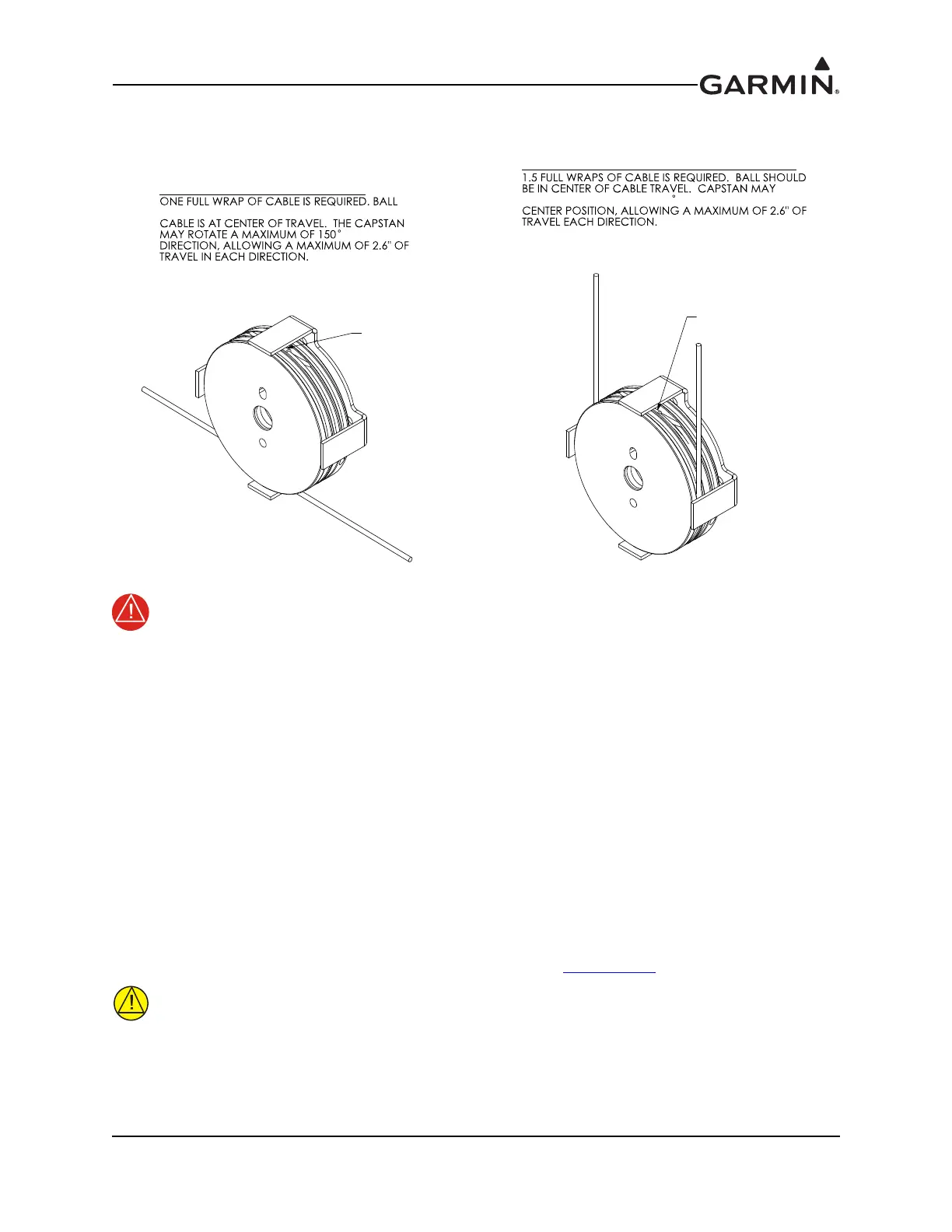
Garmin recommends using the cable arrangement (ball centered in capstan) shown in Figure 17-6 to avoid
side-loading the servo center shaft.
Figure 17-6 Cable in Capstan
The ball must be located in the center of travel on the capstan when the flight control is in
the neutral position. When the flight control is moved to the limits of its travel, the ball must
not have any possibility of exiting the capstan groove.
The bridle cable must wrap around the capstan either 1 or 1.5 full turns, as shown in Figure
17-6, and must be routed in a way that avoids the possibility of binding.
If the installation would require more than +/- 150° of capstan rotation or more than +/- 2.6
inches of cable travel, the GSA 28 servo and capstan cannot be used.
Failure to closely follow the capstan installation guidance in this section could cause the
aircraft flight controls to jam, resulting in serious injury or death
The 011-02952-02 capstan kit is provided with four #4-40 screws and lock washers for attaching the cable
guard. The screws provided are 0.25” long. This length of screw is appropriate if there is no bracket or
spacers in-between the cable guard and servo. If a mounting bracket or spacers of thickness .056” or
greater will be place in-between the stop bracket and servo, longer screws should be used to attach the
cable guard. It is recommended the thread engagement into the GSA 28, as measured from the front face
of the servo shall be 0.112” – 0.25”. If screws other than what is provided will be used, be sure to use
thread locking compound or a proper thread locking patch combined with the lock washers provided. Also
be sure to follow the recommended tightening torque specified in Figure 17-8.4
.
If screws are being used to mount the cable guard to the front face of the GSA 28 are
different than the screws provided with the stop bracket kit, care must be taken to ensure
these screws are not long enough to contact moving parts inside the GSA 28. Maximum
screw insertion, as measured from the front of the GSA 28, must be less than 0.25” to
avoid contact with parts inside the GSA 28.
BOTH CABLES EXITING CAPSTAN IN SAME DIRECTION
ROTATE A MAXIMUM OF 150
EITHER DIRECTION FROM
BALL
CABLE EXITING IN OPPOSITE DIRECTION
SHOULD BE IN CENTER OF CABLE WRAP WHEN
IN EITHER
BALL
 Loading...