190-01115-01 G3X/G3X Touch Installation Manual - GMU 22 Installation
Rev. AC Page 15-4
15.4.1 Consideration for Wing Grounded Lighting Fixtures
The following installation practices are recommended if the required GMU 22 mounting bracket is located
in the wing.
The wing tip lights should not have a power ground referenced to the chassis of the light assembly that
would then be referenced back to the airframe ground via the light assembly mounting.
A dedicated power ground should be used and returned as a twisted pair with the power source back into
the fuselage for a wing mounted GMU 22.
These installation practices will prevent magnetically interfering currents from flowing in the wing skin
that encloses the GMU 22. Electrically isolating the light assembly should not be used as an alternative to
item 1 above, unless the isolated light assembly has been analyzed for adequate protection against direct
attachment of lightning.
Refer to Section 15.5
for outline and installation drawings.
15.4.2 ADAHRS (GSU 25/73) to GMU 22 Interconnect Harness Fabrication Instructions
Table 15-5 lists parts needed for the GMU 22 interconnect harness. Some of the parts for installation are
included in the GMU 22 Connector Installation Kit. Other parts are provided by the installer. Reference
numbers refer to item bubble numbers shown in Figure 15-7
.
Table 15-6 lists material in the GMU 22 connector kit and the associated reference number, as shown in
Figure 15-7
. The GMU 22 magnetometer has an attached pigtail with male polarity. The harness
connector for the GMU 22 has female polarity.
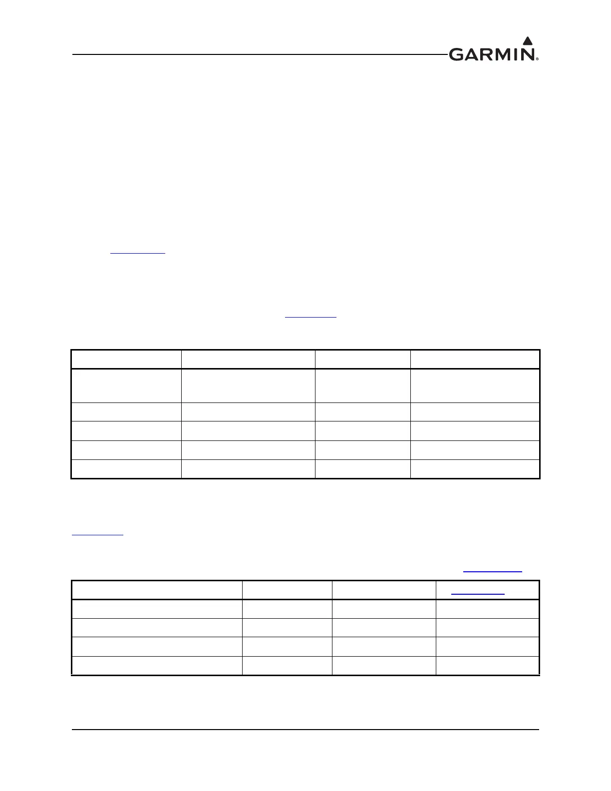
Table 15-5 Parts Needed for GMU 22 Installation
Figure D-2.4 Ref Description Qty. Included GPN or MIL Spec
1
Shield Termination
(method optional)
0
Parts used depend on
method chosen
2 Shield Extension Wire 0 M22759/16-22
3, 4, 9 GMU 22 Connector Kit* 1 011-00871-00
5 3-Conductor Cable 0 M27500-22TE3T14
6 2-Conductor Cable 0 M27500-22TE2T14
*Included in G3X w/GSU 73 Installation Kit (K10-00017-00)
Table 15-6 GMU 22 Connector Kit (011-00871-00)** Contents, Reference Figure 15-7
Item Garmin P/N Quantity Figure 15-7 Ref
Screw,6-32x.250,PHP,BR,w/Nyl 211-60037-08 3 9
Conn,Circular,Female,9 Ckt 330-00360-00 1 4
Backshell,Circular,Kit,SS 330-90005-01 1 4
Cont,Sckt,Mil Crp,Size 20 336-00022-00 10 3
**Included in G3X w/GSU 73 Installation Kit (K10-00017-00)

 Loading...