190-01115-01 G3X/G3X Touch Installation Manual - Engine/Airframe Sensor Installation
Rev. AC Page 23-27
23.3.10 Bus Current
23.3.10.1 Hall Effect Ammeter Sensor
Sensor Description – Hall Effect: Amploc KEY100, +/- 100 Amp or equivalent. Sensor output is
15.9 mV/Amp. This type of sensor is applicable to all engines.
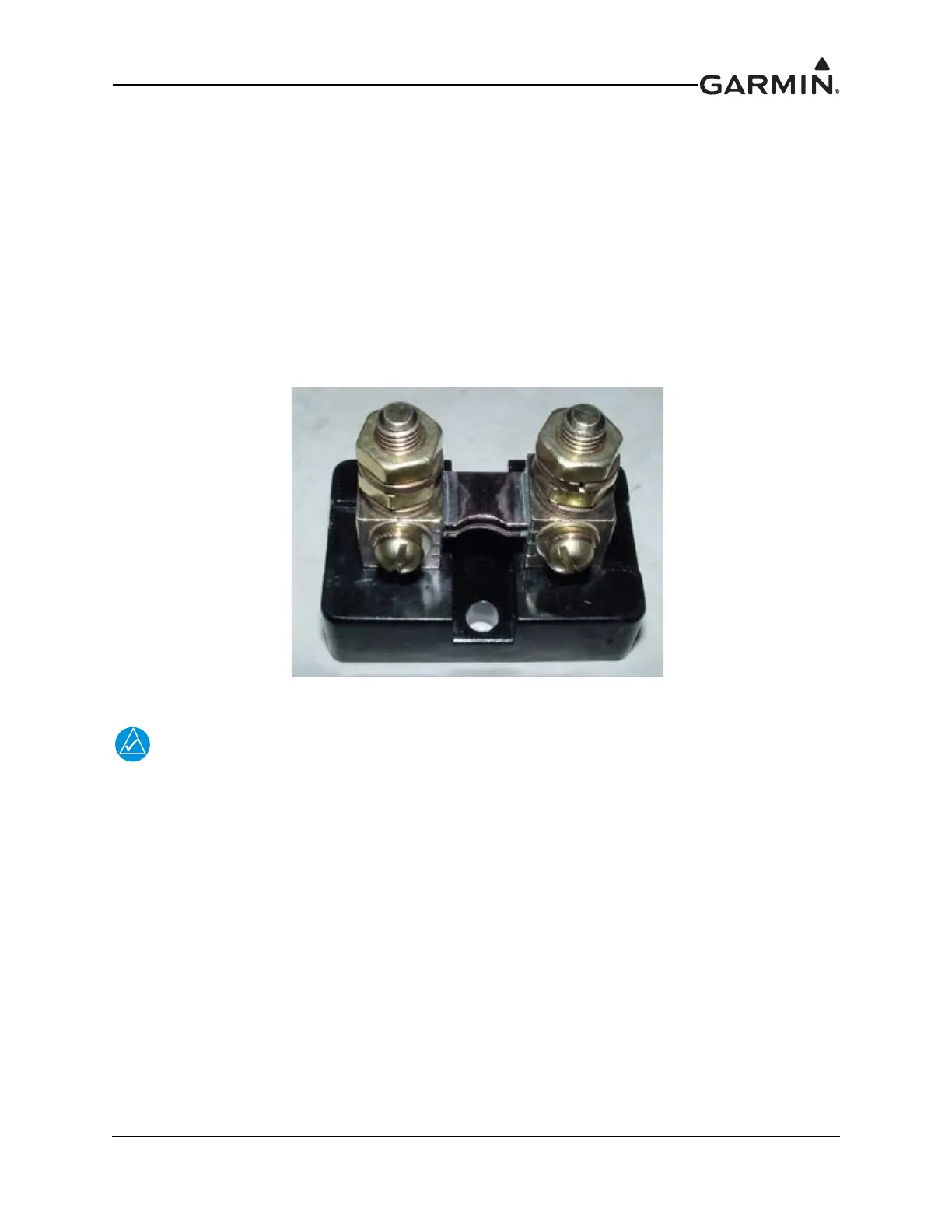
23.3.10.2 Ammeter Shunt
Sensor Description – 1C4: 100 Amp / 50 mv shunt. This type of sensor is applicable to all engines.
General Installation Guidance – Current sensing on the G3X can be done via the use of a traditional
ammeter shunt (Figure 23-17). The ammeter shunt has two holes in the base for mounting with #10
screws. The current-carrying wires are attached to the large 1/4” lugs, while the current sense wires are
attached via the use of #8 ring terminals.
Figure 23-17 Ammeter Shunt
It is important that no metal portion of the shunt touch any other portion of the aircraft or
exposed wiring. Large voltages and current are present in the shunt, and an electrical
short or fire could result from inadvertent contact.
The shunt should be installed in-line with the current being sensed. As noted below, the appropriate wire
should be cut and attached to each of the large ¼” lugs. A one amp fuse or other form of circuit protection
must be installed between the shunt and the applicable GEA 24/GSU 73 inputs to prevent inadvertent
damage to the GEA 24/GSU 73. Connect the two sense wires (attached to the #8 terminals) to the
appropriate inputs on the GEA 24/GSU 73 as referenced in the G3X interconnects in Section 29 through
Section 32. If the ammeter readings are shown with the opposite polarity, check to see if the sense wire
connections are reversed.
An alternator ammeter shunt should be installed inline in the alternator output (“B” terminal). A battery
ammeter shunt should be installed between the battery positive terminal and the battery contactor.
Depending on the location of the alternator or battery relative to its supported electrical bus, it is typically
desirable to install the shunt on the firewall near where the alternator or battery output would normally
penetrate the firewall.

 Loading...