190-01115-01 G3X/G3X Touch Install Manual - GDU 4XX Config and Post Install Checkout
Rev. AC Page 34-154
34.4.26.16 Trim/Flap Position Input
The GEA 24 and GSU 73 each have multiple POS (position) inputs. Each POS input can be used with a
resistive (potentiometer) sensor to monitor the following position measurements:
• Elevator Trim
• Aileron Trim
• Rudder Trim
• Flap Position
All POS inputs require calibration (see section
Section 34.4.26.16.1).
The GEA 24 POS 6 and POS 7 inputs require the LO side of the input to be connected to
ground. See Section 29.2
for wiring details.
Vertical Power: When using a Vertical Power unit, trim and flap positions will automatically be displayed.
Connecting, configuring, and calibrating the POS inputs is not required when the position sensors are
connected to a Vertical Power unit.
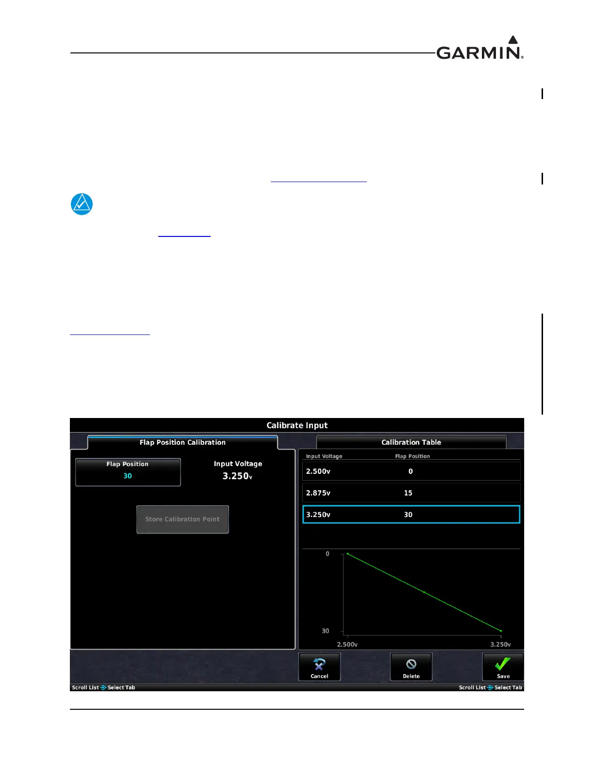
34.4.26.16.1 Trim/Flap Position Input Calibration
The process for calibrating trim/flap position inputs is similar to the process described in
Section 34.4.26.25
, except the raw sensor values are read directly from the position sensors instead of
being entered manually by the installer. This allows precise calibration based on moving the control
surfaces to known positions during the calibration procedure.
To calibrate trim/flap position inputs:
1. From the POS input configuration page, press the Calibrate button to display the Calibration Page.

 Loading...