190-01115-01 G3X/G3X Touch Install Manual - GDU 4XX Config and Post Install Checkout
Rev. AC Page 34-141
EIS Input Calibration - Some EIS inputs require calibration to convert from raw input values (typically
voltage or frequency) to calibrated values for display. The most frequently used page for EIS input
calibration allows the installer to specify a calibration curve from a series of raw and calibrated values.
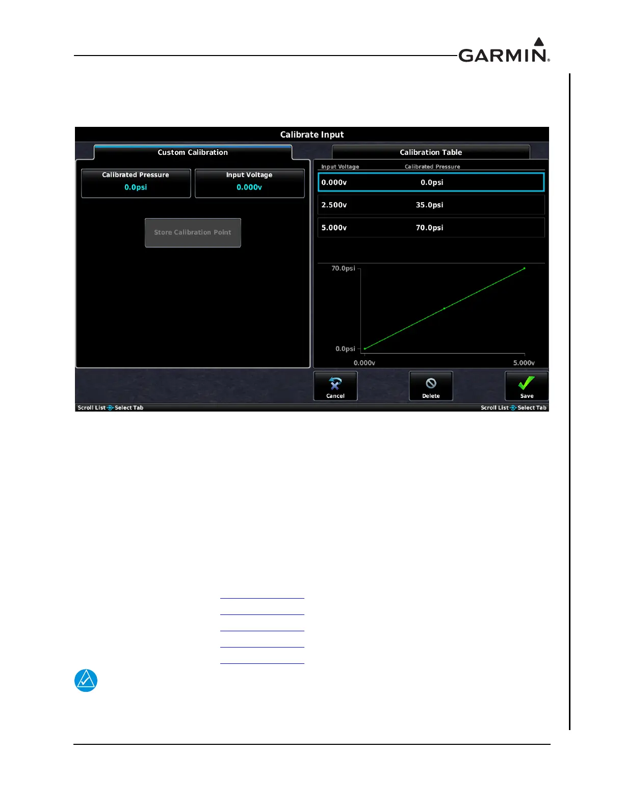
Figure 34-42 Engine Input Calibration Page (Example)
In general, the procedure for calibrating EIS inputs is as follows:
1. From the EIS input configuration page, press the Calibrate button to display the Calibration Page.
2. Enter values for Calibrated Value and Input Voltage (or Input Frequency, for digital inputs).
3. Press the Store Calibration Point button to add a calibration point.
4. Press the Save button to and exit the calibration page.
5. On the EIS input configuration page, press the Save button to store calibration data.
The greater number of calibration points that are used, the more accurate the calibration will be. A yellow
line on the graph indicates potentially incorrect/invalid calibration.
Refer to the following sections for additional information about EIS input calibration:
• Fuel Quantity Section 34.4.26.12
• Trim/Flap Position Section 34.4.26.16
•Bus Voltage Section 34.4.26.14
•Current Section 34.4.26.15
• Custom EIS Inputs Section 34.4.26.25
User-defined (“Custom”) EIS inputs requiring calibration will display “---” in place of
the number if the input value exceeds the limits of the installer-defined calibration. This
can be avoided by entering calibration points that exceed the expected input range.

 Loading...