190-01115-01 G3X/G3X Touch Installation Manual - GAP 26 Installation
Rev. AC Page 5-2
5.2 Equipment Available
5.3 Required Equipment
• GAP 26 Pitot/AOA Probe (010-01074-00, 010-01074-10, or 010-01074-20)
• Electrical and pneumatic connectors per installer preference. For heated probe installations where
the installer desires to shorten the provided aluminum tubing, a minimum of 8 inches of aluminum
tubing should remain between the probe and any transition to non-metallic tubing to protect the
non-metallic tubing from excessive heat.
• Mount: Standard AN5812 pitot tube mount.
• #6-32 screws (4 pcs), required length (.218” min - .312” max), recommend screws with nylon
patch on threads for thread locking for mounting probe.
• #4 or #6 (4 pcs) pan or hex head screws for mounting heater control box.
5.4 General Specifications
See Section 2.2 for power/current specifications, and Section 2.4.1 for dimension/weight specifications.
5.5 Unit Installation
Fabrication of a wiring harness is required. Sound mechanical and electrical methods and practices are
recommended for installation of the GAP 26. Refer to Section 2.3
for wiring considerations (-10 and -20
units only).
5.5.1 Mounting Location
• The GAP 26 is an under-wing mounted pitot/AOA probe, it is not intended for fuselage mount
applications. For proper functionality, the GAP 26 should be mounted in a location where airflow
over the probe is relatively undisturbed (typically mid-wing span).
• The tip of the GAP 26 should be located at least 4” from, but not more than 10” below the bottom
surface of the wing. The probe tip may protrude up to 2” max in front of the leading edge of the
wing.
• Viewed from the side, the GAP 26 probe bayonet centerline should be mounted within ±5° from
parallel to the wing chord line.
• Viewed from the top, the GAP 26 bayonet centerline should be mounted within ±5° from parallel
with the aircraft centerline.
• Consider using the aircraft designer/manufacturer’s recommended mounting location (if
specified). Optimal AOA functionality results when the tip of the GAP 26 probe is located no
further back than 25% of the wing chord length from the leading edge. (See Figure 5-2
)
• The 3/16” diameter aluminum pneumatic tubing is intended to be hand bendable to suit various
mounting configurations. Minimum allowable bend radius is 1.5”. It is recommended to bend any
given section only once to prevent work hardening and cracking of the aluminum tubing.
• Garmin recommends that the GAP 26 not be used on aircraft where the ship static pressure port is
located under the wing (due to the likelihood that the AOA measurement will be significantly
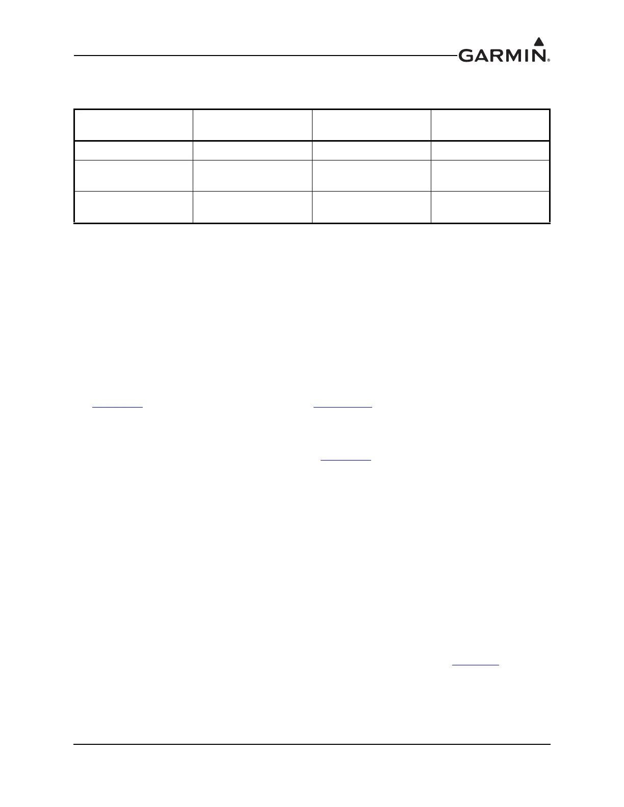
Table 5-1 GAP 26 Part Numbers
Model
Assembly Part
Number
Unit Only Part
Number
Heater Control Box
Part Number
GAP 26 Probe Only 010-01074-00 011-02964-00 N/A
GAP 26 Probe Only,
Heated
010-01074-10 011-02964-10 N/A
GAP 26 Probe Only,
Heated, Regulated
010-01074-20 011-02964-20 011-02965-00
 Loading...