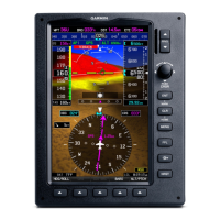
190-01115-01 G3X/G3X Touch Installation Manual - GDU 46X Installation
Rev. AC Page 8-3
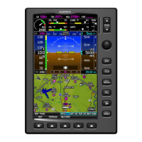
8.3.1.1 GDU 46X PFD Configuration Module
The GDU 46X PFD 1 display uses a configuration module designated as the master system configuration
module. The master system configuration module stores configuration data identical to the PFD
configuration data stored in the PFD memory. The PFD cross-checks the configuration module data
against internal PFD memory and self-configures to match the master system configuration module. The
PFD also maintains control of other LRUs’ configuration and calibration settings except for GSU 73
AHRS calibration settings which are stored in the GSU 73 configuration module (the GSU 25 does not
have a configuration module). This allows critical data to be retained with the airframe even if the PFD 1
display is replaced.
8.3.2 Additional Equipment Required
A 3/32” hex drive tool is required to secure the GDU 46X to the panel as described in Section 8.6.1
Unit
Installation and shown in Figure 8-4
.
8.4 Unit Installation
Fabrication of a wiring harness is required. Sound mechanical and electrical methods and practices are
recommended for installation of the GDU 46X. Refer to Section 2.3
for wiring considerations, and to
Section 25.4
for pinouts.
Connector kits include backshell assemblies. Garmin’s backshell connectors give the installer the ability
to quickly and easily terminate shield grounds at the backshell housing. The instructions needed to
assemble the backshell connector w/Shield Block grounding system are located in Section 24
.
Replacement cursor knobs (part number K00-00578-00) for the GDU 46X are available from a Garmin
dealer.
Figure 8-2 Grounded Connector Shell
Table 8-2 Contents of GDU 46X Connector Kit (011-01921-10)*
Item Garmin P/N Quantity
Sub-Assy, bkshl w/Hdw, Jackscrew 011-01855-04 1
Conn, Rcpt, D-Sub, Crimp Socket 330-00625-50 1
Contact, Sckt, D-Sub, Crimp, Size 20 336-00022-02 30
GDU 46X
SIGNAL GROUND
P4602
GARMIN SHIELD
BLOCK GROUND
 Loading...
