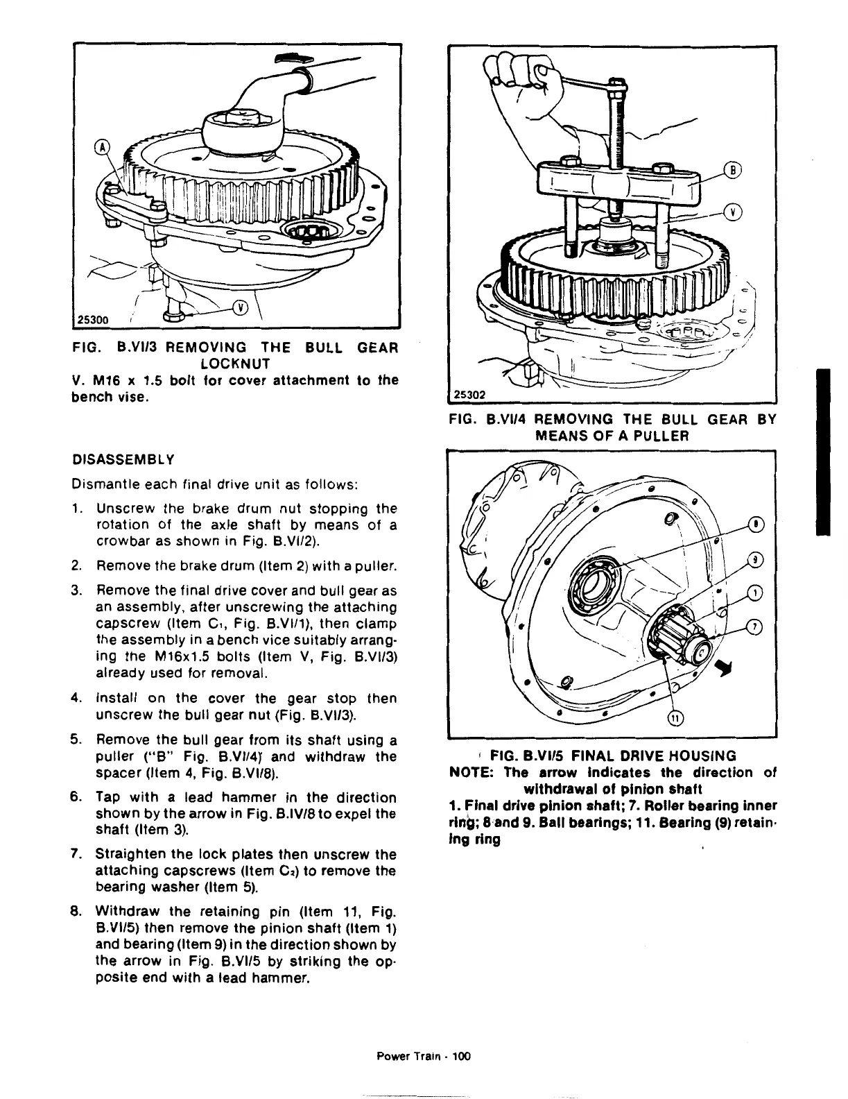
FIG. B.VI/3 REMOVING THE BULL GEAR
LOCKNUT
V.
M16 x 1.5
bolt
for
cover
attachment
to
the
bench vise.
DISASSEMBLY
Dismantle each final drive
unit
as follows:
1.
Unscrew the brake drum nut stopping the
rotation of the axle shaft by means
of
a
crowbar as shown in Fig. B.VI/2).
2.
Remove the brake drum (Item
2)
with
a puller.
3.
Remove the final drive cover and bull gear as
an assembly, after unscrewing the
attaching
capscrew
(Item
c,,
Fig. B.VI/1), then clamp
the assembly in a bench vice suitably arrang-
ing
the
M16x1.5
bolts
(Item
V,
Fig. B.VI/3)
already used for removal.
4.
Install on the cover the gear
stop
then
unscrew
the bull gear
nut
(Fig. B.VI/3).
5.
Remove the bull gear from
its
shaft using a
puller
("8"
Fig. B.VI/41 and withdraw the
spacer (Item
4,
Fig. B.VI/8).
6.
Tap
with
a lead hammer in the
direction
shown by the arrow in Fig. B.IV/8
to
expel the
shaft
(Item
3).
7.
Straighten the
lock
plates then unscrew
the
attaching
capscrews (Item
C2)
to
remove the
bearing washer (Item
5).
8.
Withdraw
the retaining pin (Item 11, Fig.
B.VI/5) then remove the
pinion
shaft (Item
1)
and bearing (Item
9)
in the
direction
shown by
the arrow in Fig. B.VI/5 by
striking
the op-
posite
end
with
a lead hammer.
25302
FIG. B.VI/4 REMOVING THE BULL GEAR BY
MEANS OF A PULLER
1
FIG. B.VI/5
FINAL
DRIVE HOUSING
NOTE: The arrow
Indicates
the
direction
of
withdrawal
of
pinion
shaft
1. Final drive
pinion
shaft;
7.
Roller bearing
inner
ring; 8·and 9. Ball bearings; 11. Bearing
(9)
retain·
lng
ring
Power Train · 100

 Loading...
