25290
Dr·-
-Qc.
•QZ
1---i------!lS
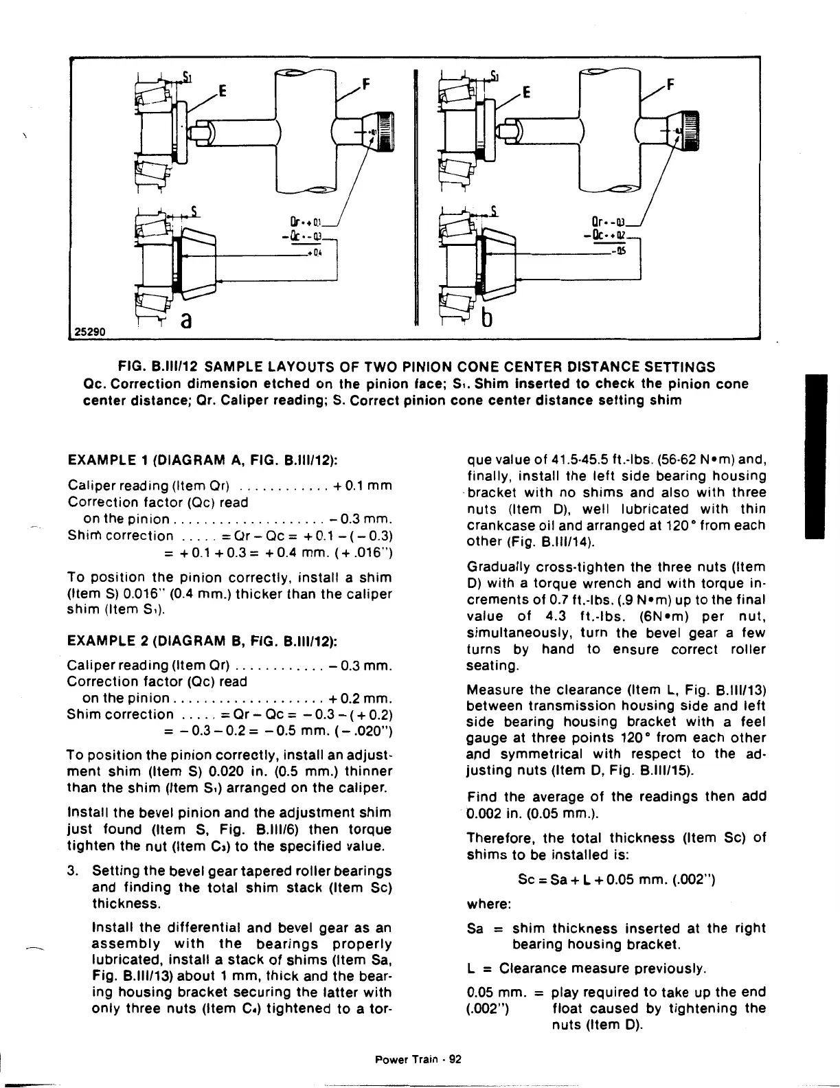
FIG.
8.111112
SAMPLE LAYOUTS OF TWO PINION CONE CENTER DISTANCE SETTINGS
Oc. Correction
dimension
etched
on the
pinion
face; s
..
Shim
inserted
to
check
the
pinion
cone
center
distance; Or. Caliper reading;
S.
Correct
pinion
cone
center
distance
setting
shim
EXAMPLE 1 (DIAGRAM A, FIG.
8.111112):
Caliper reading (Item Or)
............
+
0.1
mm
Correction factor (Oc) read
on the
pinion
....................
-0.3
mm.
Shim correction
.....
= CJr- Oc = +
0.1
-
(-
0.3)
= +0.1
+0.3=
+0.4
mm.
(+.016")
To
position
the
pinion
correctly, install a shim
(Item
S)
0.016" (0.4 mm.)
thicker
than the
caliper
shim
(Item S.).
EXAMPLE 2 (DIAGRAM
8,
FIG.
8.111112):
Caliper reading (Item Or)
............
-0.3
mm.
Correction
factor
(Oc) read
on the
pinion
....................
+ 0.2 mm.
Shim
correction
.....
=Or-
Oc = -
0.3-
( + 0.2)
= -
0.3-
0.2 =
-0.5
mm.
(-
.020")
To
position
the
pinion
correctly,
install an
adjust·
ment
shim
(Item
S)
0.020 in. (0.5 mm.)
thinner
than the
shim
(Item
s,)
arranged on the caliper.
Install the bevel
pinion
and the
adjustment
shim
just
found (Item
S,
Fig.
8.11116)
then torque
tighten
the
nut
(Item
c,)
to
the
specified
value.
3.
Setting
the
bevel gear tapered
roller
bearings
and
finding
the
total
shim
stack
(Item Sc)
thickness.
Install
the
differential
and bevel gear as
an
assembly
with
the
bearings
properly
lubricated,
install
a
stack
of
shims
(Item
Sa,
Fig.
8.111113)
about
1 mm,
thick
and the bear-
ing
housing
bracket
securing
the
latter
with
only
three
nuts
(Item
c.)
tightened
to
a tor-
Power Train ·
92
que value
of
41.5·45.5 ft.·lbs. (56·62
N•m)
and,
finally, install the
left
side bearing
housing
·bracket
with
no
shims
and also
with
three
nuts
(Item
D),
well lubricated
with
thin
crankcase oil and arranged at 120 o from each
other
(Fig.
8.111114).
Gradually cross·tighten the three nuts (Item
D)
with
a torque wrench and
with
torque in·
crements
of
0.7 ft.·lbs.
(.9
N•m)
up to the final
value
of
4.3
ft.·lbs.
(6N•m)
per
nut,
simultaneously,
turn
the bevel gear a few
turns by hand
to
ensure correct roller
seating.
Measure the clearance (Item
L,
Fig.
8.111113)
between
transmission
housing
side and
left
side bearing housing bracket
with
a feel
gauge at three
points
120 o from each
other
and symmetrical
with
respect
to
the ad·
justing
nuts
(Item
D,
Fig.
8.111115).
Find the average
of
the readings then add
0.002 in. (0.05 mm.).
Therefore,
the
total
thickness
(Item Sc)
of
shims
to
be installed is:
Sc
=Sa+
L + 0.05 mm. (.002")
where:
Sa
=
shim
thickness
inserted at the right
bearing
housing
bracket.
l = Clearance measure previously.
0.05 mm.
= play required
to
take up the end
(.002") float caused by
tightening
the
nuts
(Item
D).
 Loading...

