FIG. B.l/2 RIGHT SIDE VIEW OF TRACTOR
WITHOUT REAR HOOD AND FUEL TANK
CJ.
Upper
screws
securing
the
clutch·
transmission
housing
to
the engine crankcase;
Fe.
Electric cable strap; c, and
Ca.
Tank supports
front and rear attaching capscrews;
18. Fuel tank
supports
10" CLUTCH REMOVAL
Split the engine
with
front axle
as
an
assembly
from the tractor
transmission
housing (Fig. B.l/3)
and then remove the
clutch
unit from the engine
flywheel as follows:
A
1.
Disconnect the battery ground cable and
protect the terminal.
2. Remove, in
the
following
order:
The hood back plate, and from
this
remove
the lighting-starting
switch.
The rear hood after separating
it
from the
side panels and dashboard.
The
dashboard,
disconnecting
the
tachourmeter cable,
electrical
connections
and starting
switch
unit.
The fuel tank
after
closing
the
drain cocks,
disconnecting
the
fuel level
indicator
wires
and fuel Jines and removing
the
mounting
brackets.
3.
Disconnect
the
electric
cables from the
engine starting safety push-button and from
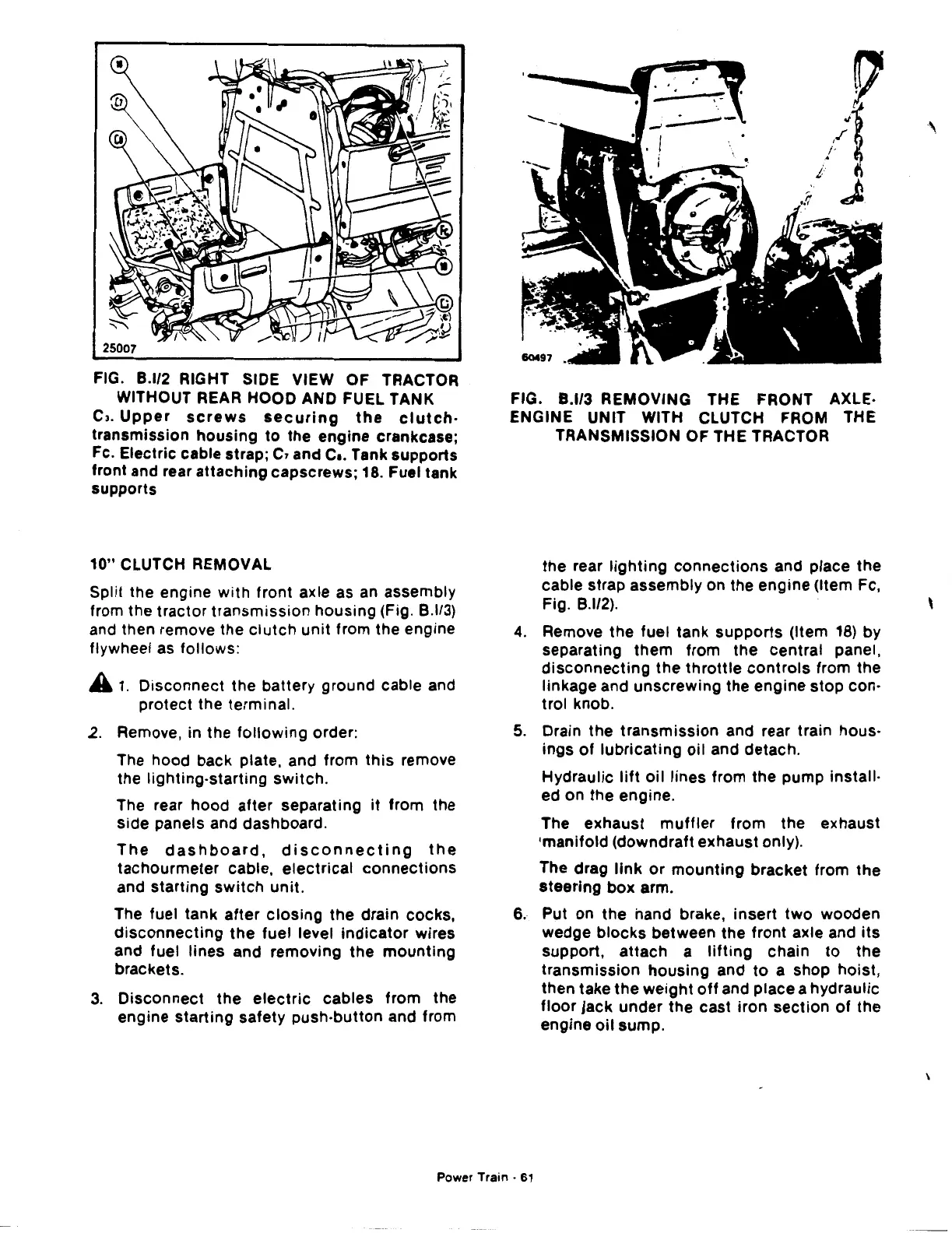
FIG.
B.l/3 REMOVING THE FRONT AXLE·
ENGINE UNIT WITH CLUTCH FROM THE
TRANSMISSION OF THE TRACTOR
the rear
lighting
connections
and place
the
cable strap assembly on the engine (Item Fe,
Fig.
8.112).
4.
Remove
the
fuel tank
supports
(Item
18)
by
separating them from
the
central panel,
disconnecting
the
throttle
controls
from the
linkage and unscrewing the engine stop con-
trol knob.
5.
Drain the transmission and rear train hous-
ings
of
lubricating
oil
and detach.
Hydraulic
lift
oil
lines from the pump install-
ed on the engine.
The exhaust
muffler
from the exhaust
•manifold (downdraft exhaust only).
The drag
link
or
mounting
bracket from
the
steering box arm.
6. Put on
the
hand brake,
insert
two
wooden
wedge
blocks
between the front axle and
its
support, attach a
lifting
chain
to
the
transmission
housing
and
to
a shop hoist,
then take
the
weight
off
and place a hydraulic
floor
jack under the cast iron section
of
the
engine
oil
sump.
Power
Train·
61
'
 Loading...

