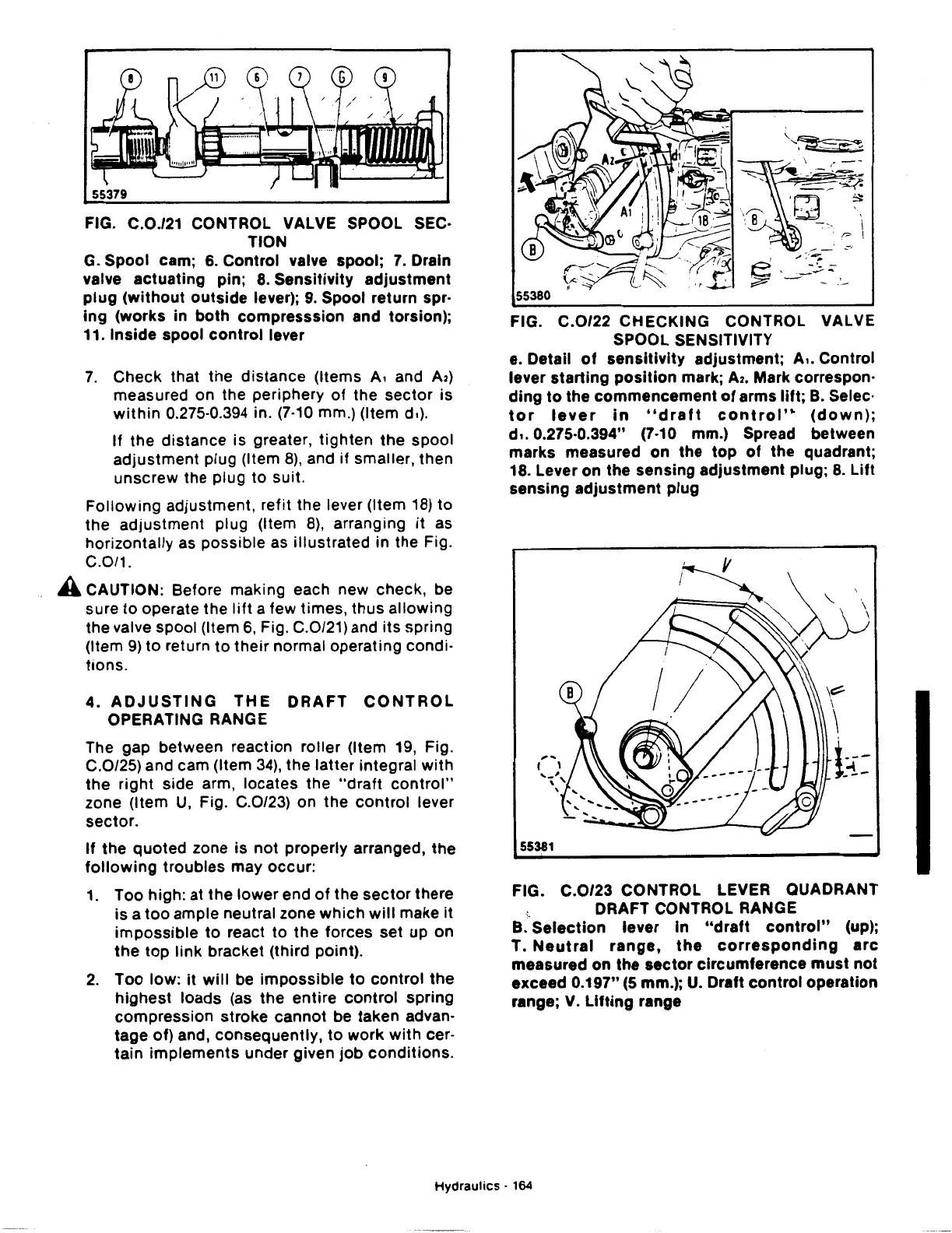
FIG. C.0./21 CONTROL VALVE SPOOL SEC·
TION
G. Spool cam;
6.
Control valve spool;
7.
Drain
valve actuating pin;
8.
Sensitivity
adjustment
plug
(without
outside
lever);
9.
Spool return spr·
ing
(works
in
both
compresssion and torsion);
11. Inside spool
control
lever
7.
Check that the
distance
(Items
A,
and
A2)
measured on the periphery
of
the
sector
is
within
0.275·0.394 in. (7·10 mm.) (Item d.).
If
the
distance is greater,
tighten
the
spool
adjustment
plug (Item
8),
and
if
smaller, then
unscrew the plug to suit.
Following
adjustment, refit the lever (Item
18)
to
the
adjustment
plug (Item
8),
arranging it as
horizontally as possible as illustrated in the Fig.
C.0/1.
A CAUTION: Before making each new check, be
sure
to
operate the
lift
a few times, thus allowing
the valve spool (Item
6,
Fig. C.0/21) and
its
spring
(Item
9)
to
return
to
their
normal operating condi·
tions.
4.
ADJUSTING
THE
DRAFT
CONTROL
OPERATING RANGE
The gap between reaction roller (Item 19, Fig.
C.0/25) and cam (Item
34),
the latter integral
with
the
right side arm, locates the
"draft
control"
zone (Item
U,
Fig. C.0/23) on
the
control
lever
sector.
If
the
quoted
zone is
not
properly arranged, the
following
troubles
may occur:
1.
Too high: at
the
lower end
of
the
sector
there
is a
too
ample neutral zone which
will
make it
impossible
to
react
to
the
forces set up on
the top
link
bracket (third point).
2.
Too
low:
it
will
be
impossible
to
control
the
highest
loads (as
the
entire
control
spring
compression
stroke cannot be taken advan·
tage of) and, consequently,
to
work
with
cer-
tain
implements
under given
job
conditions.
--·
,::'1
~
...
:~-
~"
__
__...._
~
- -
.'-
VALVE
e. Detail
of
sensitivity
adjustment; A,. Control
lever
starting
position
mark;
A2.
Mark correspon·
ding
to
the commencement
of
arms lift; B. Selec·
tor
lever
in
"draft
control'..
(down);
d
•.
0.275·0.394" (7·10 mm.) Spread between
marks measured on the
top
of
the quadrant;
18. Lever on the sensing adjustment plug;
8.
Lift
sensing
adjustment
plug
55381
FIG.
C.0/23
CONTROL LEVER QUADRANT
.•.
DRAFT CONTROL RANGE
B.
Selection
lever In
"draft
control"
(up);
T.
Neutral
range,
the
corresponding
arc
measured on
the
sector
circumference
must
not
exceed 0.197"
(5
mm.);
U.
Draft
control
operation
range; V.
Lifting
range
Hydraulics
· 164
 Loading...

