ASSEMBLING THE WHEEL HUB
Press
into
the wheel hub
(10)
the tapered roller
bearing
outer
races
(9
and
11
).
Fill
with
lithium
- base
lubricant
grease
the
hub
inside between
the
two
bearings
prior
to
mounting
on
the
flange
the
outer
tapered roller bearing inner race.
ADJUSTMENT OF WHEEL HUB BEARINGS
Tighten the first splined
nut
(Item S11, Fig.
B.IX/10) by
continuous
rotation
of
the
hub
in both
directions
until
feeling a
slight
braking; then
screw back the splined nut in order to permit a
free rotation
of
the hub
without
any play. Bend a
washer edge
(7)
into
one groove
of
the nut and
tighten
the second splined nut at a torque of
362·434 ft. lbs. (491-588 N-m).
Introduce inside
lithium
base lubricant grease.
REMARKS: The
two
splined nuts
must
be
fitted
having
the
outer chamfering towards
the bearings, as indicated on Fig.
B.IX/1
1.
Fit the splined hub
(6)
by tightening the screws
with
self-locking at a torque
of
65·72
ft.lbs.
(88-98
N-m).
Repeat the procedure for the left side.
SETTING THE FRONT DRIVE AXLE
Fit the driving wheels,
completely
assembled
with
transversal drag link.
Tighten the self-locking
nuts
and the universal
shaft
coupling
flange retaining screws at a tor-
que value
of
36·40 ft. lbs. (49·54 N-m).
Fill the casing
with
oil
by the plug (T, Fig. B.IX/3).
When carrying out
the
assembling operations,
repeat the reverse procedure as indicated for
removal.
After
finishing
the reassembling, grease the
splined
joint
and
the
universal
joint
until
the
grease leaks out by the universal
joint
central
trap. To carry
out
this
operation use a grease
gun.
RUNNING-IN OF THE FRONT DRIVE AXLE
Grease
with
lubricant
grease the
joint
locations
through
the
threaded plug holes provided
with
sealing rings.
Tighten
the
greasers
into
the
wheel
hubs
and
steering levers.
Fill the
differential
casing
with
the recommend-
ed
oil
up
to
the
level
of
the plug.
Fit
on
the
running-in bench the front driver axle
and
let
it
operate for 5
minutes
at a speed
of
1800
rpm.
At
the
same time, check for:
abnormal noise exceeding the medium level.
oil
leakages at
joints
and seatings.
abnormal heating
of
the moving parts.
if
the hub presents a
slight
vibration within
the permitted angle by the stop plates.
INSPECTION
Make sure that the nuts
anQ
the screws from the
above-mentioned table are tightened to the tor·
que
specification
and that they are secured.
Make sure the running-in period of 5
minutes
is
carried out; during the running-in the front drive
axle
must
strictly
comply
with
as
follows:
front
drive axle must not get hot;
front
drive axle
must
not
present abnormal
noise;
no leakages are permitted;
the steering levers
must
easily rotate:
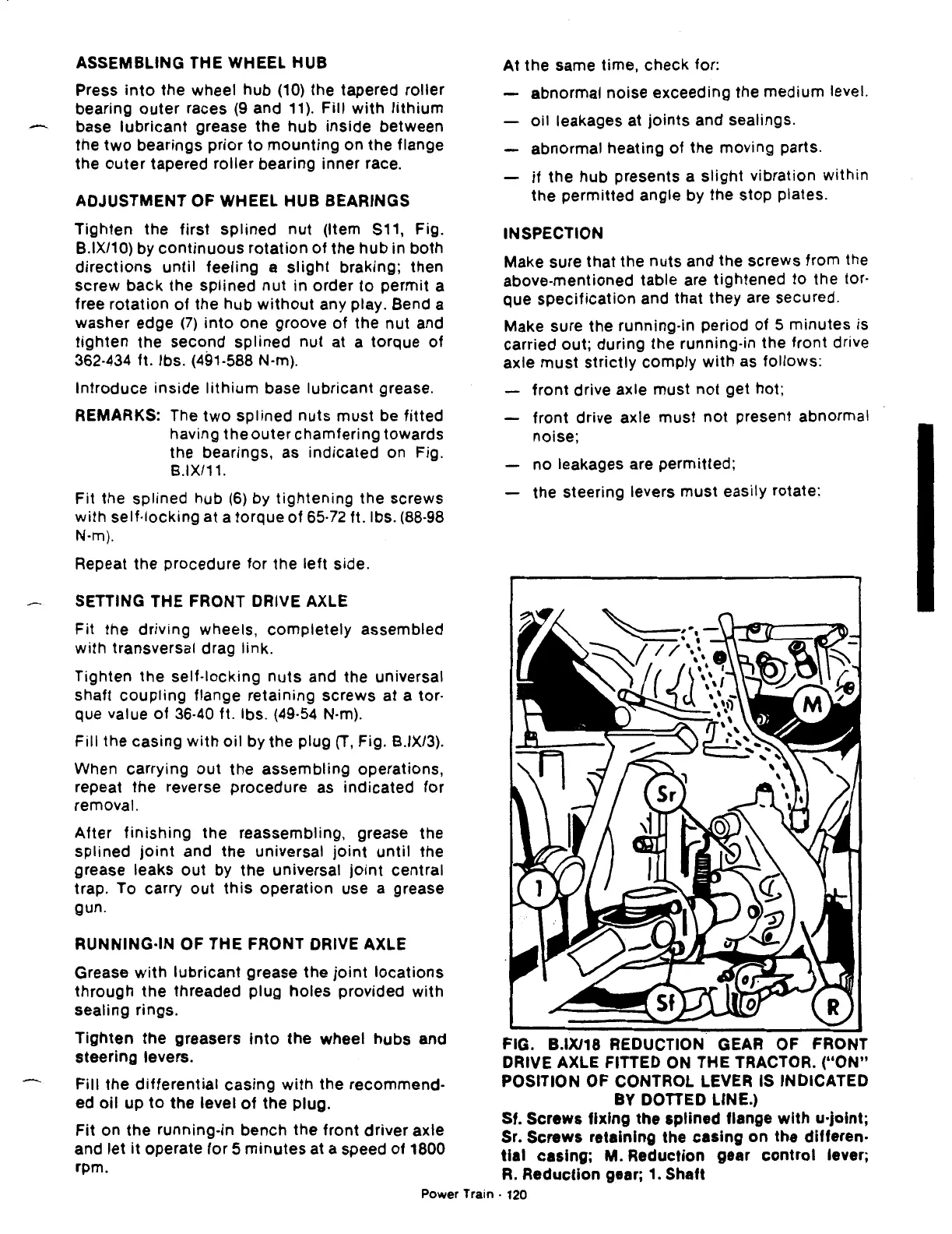
FIG. B.IX/18 REDUCTION GEAR OF FRONT
DRIVE AXLE FITTED
ON
THE TRACTOR.
("ON"
POSITION OF CONTROL LEVER IS INDICATED
BY DOTTED LINE.)
Sf. Screws fixing the
splined
flange
with
u-joint;
Sr. Screws retaining the casing on the differen·
tial
casing; M. Reduction gear
control
lever;
R.
Reduction gear;
1.
Shaft
Power Train · 120
 Loading...

