FIG. A.ll/11 ROCKER ARMS AND THEIR SUP·
PORTS, SPRINGS AND SHAFTS
(C,.) Valve-to-rocker arm gap
adjusting
screw;
(C
•.
) Screw; (C,.)
locknut;
(Ca.)
Screw
with
lubricating
oil
hole securing rocker arm supports
to
shafts;
21.
End washer;
22.
Spring;
23.
Rocker
arm shaft; 24. Rocker arm
shaft
support;
25.
Rocker arm;
26.
End cup;
27.
Split
dowel;
a.
Third
cylinder
rocker arm
support
Inspect contact surfaces
of
adjusting
screws
and rods which should be glass-smooth,
with
no
seizure marks. Check the rocker arm spacer spr-
ings (Item
22,
Fig. A.ll/1
1)
and measure
their
strain values (see "Torque
Specifications"
table).
Install the rocker arms and make sure that:
1.
Lubrication
passages
are
free
and
unobstructed.
2.
End cups are 0.03 -
0.04
in.
(0.9
·
1.1
mm.)
thick.
3.
Spring end spacers are 1 mm. (0.040 in.)
thick.
TIMING GEAR ASSEMBLY
To gain access
to
the
timing
gears remove the
case cover (Fig. A.ll/13) as
outlined
under "Cam-
shaft Removal".
Remove the
timing
gears from the case as
follows:
1.
Camshaft driving gear (Item
10):
(see
instruc·
tions
under
"Camshaft
Removal".)
2.
Idler gear (Item
29):
remove snap ring first,
then withdraw
it
together
with
the
two
thrust
washers.
3.
Fuel supply pump driving gear (Item
31).
First
remove the pump
with
its
cam drive gear
bearing (Item
2,
Fig. A.IV/2) then remove the
shaft retaining ring and
withdraw
the shaft
with
gear (Item
31).
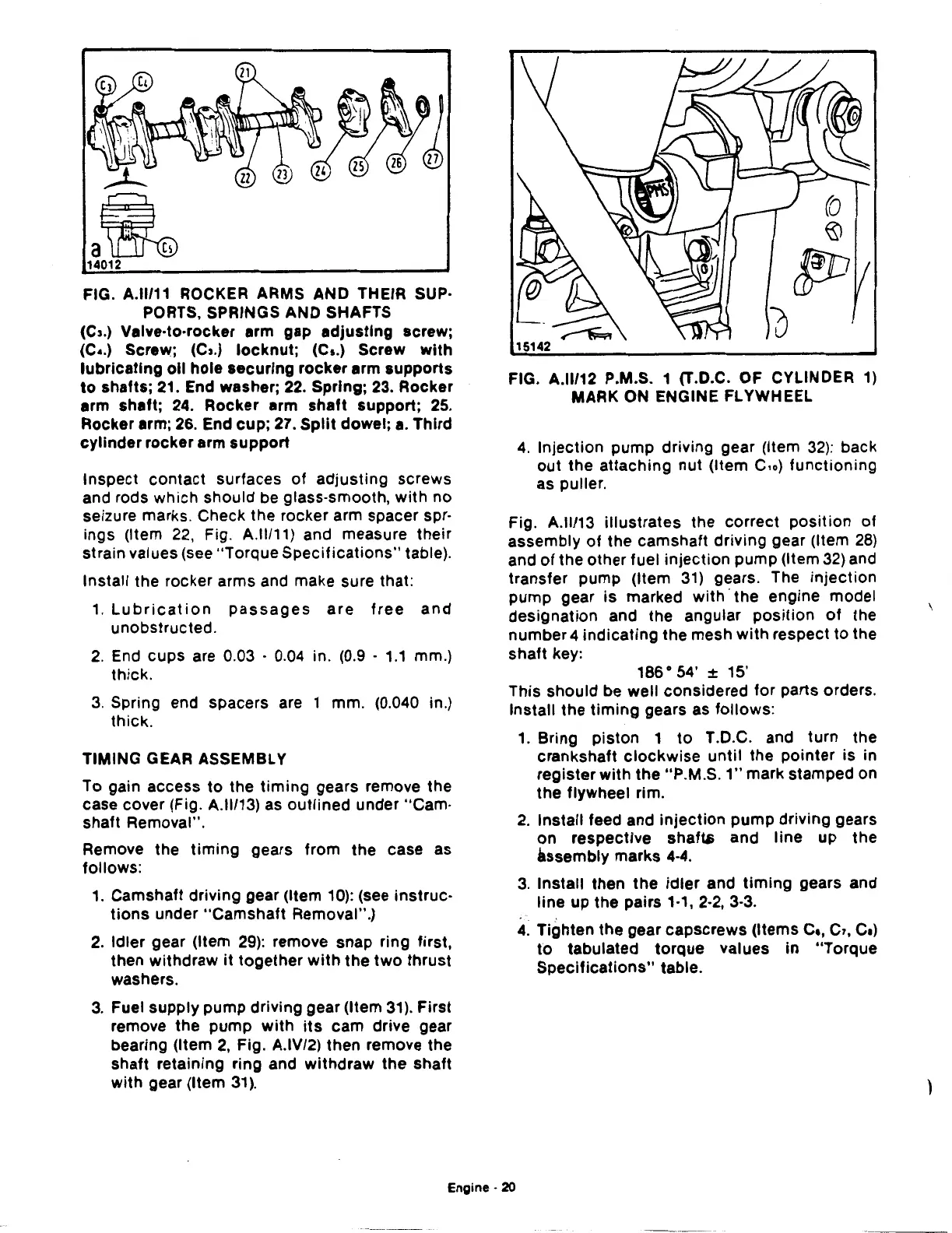
FIG. A.ll/12 P.M.S. 1 (T.D.C. OF CYLINDER
1)
MARK ON ENGINE FLYWHEEL
4.
Injection pump driving gear (Item
32):
back
out
the attaching nut (Item
C.o)
functioning
as puller.
Fig. A.ll/13 illustrates the correct position
of
assembly
of
the camshaft driving gear (Item
28)
and
of
the other fuel injection pump (Item
32)
and
transfer pump (Item
31)
gears. The
injection
pump gear
is
marked
with·
the engine model
designation and the angular
position
of
the
number 4 indicating the mesh
with
respect
to
the
shaft key:
186° 54'
± 15'
This should be well considered for parts orders.
Install the
timing
gears as follows:
1.
Bring piston 1
to
T .D.C. and turn the
crankshaft
clockwise
until the pointer is in
register
with
the "P.M.S.
1"
mark stamped on
the flywheel rim.
2.
Install feed and injection pump driving gears
on
respective
shafw
and line up the
assembly marks
4-4.
3.
Install then
the
idler
and
timing
gears and
line up the pairs 1·1, 2·2, 3-3.
4.
Tighten the gear capscrews (Items
c.,
C1,
Ce)
to
tabulated torque values in "Torque
Specifications"
table.
Engine·
20
\
 Loading...

