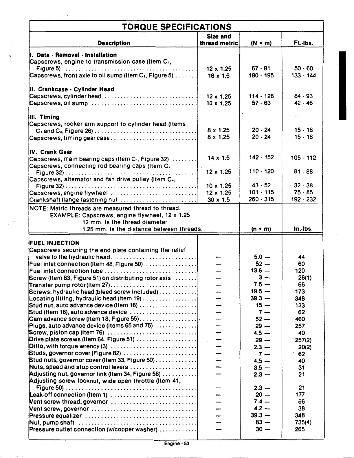
TORQUE SPECIFICATIONS
Size and
Description thread
metric
(N
• m)
I. Data • Removal • Installation
~apscrews,
engine
to
transmission case (Item
C1,
Figure
5)..........................................
12 x 1.25 67 ·
81
Capscrews, front axle to oil sump (Item
C2,
Figure
5)
. . . . . . . 16 x 1.5 180 · 195
II. Crankcase • Cylinder Head
Capscrews, cylinder head . . . . . . . . . . . . . . . . . . . . . . . . . . . . .
12 x 1.25 114 · 126
Capscrews, oil
sump
. . . . . . . . . . . . . . . . . . . . . . . . . . . . . . . . . 10 x 1.25 57 · 63
Ill.
Timing
Capscrews, rocker arm support
to
cylinder head (Items
C1
and
Cz,
Figure
26)
...............................
.
Capscrews,
timing
gear case
..........................
.
IV.
Crank Gear
Capscrews, main bearing caps (Item
c,,
Figure 32)
.......
.
Capscrews, connecting rod bearing caps (Item
Cz,
Figure
32)
........................................
.
Capscrews, alternator and fan drive pulley (Item
c.,
Figure
32)
........................................
.
Capscrews, engine flywheel
..........................
.
Crankshaft flange fastening nut
.......................
.
NOTE: Metric threads are measured thread
to
thread.
EXAMPLE: Capscrews, engine flywheel,
12
x 1.25
12
mm. is the thread diameter
1.25 mm. is the distance between threads.
FUEL INJECTION
Capscrews securing the end plate containing the relief
valve to the hydraulic head
..........................
.
Fuel inlet connection (Item
48, Figure
50)
...............
.
Fuel inlet connection tube
............................
.
Screw (Item
83, Figure 51) on distributing rotor axis
.......
.
Transfer pump
rotor
(Item 27)
..........................
.
Screws, hydraulic head (bleed screw included)
...........
.
Locating
fitting,
hydraulic head (Item
19)
................
.
Stud nut, auto advance device (Item
16)
.................
.
Stud (Item
16),
auto
advance device
....................
.
Cam advance screw (Item
18, Figure
55)
..................
.
Plugs,
auto
advance device (Items 65 and 75)
............
.
Screw, piston
cap
(Item
76)
...........................
.
Drive plate screws (Item 64, Figure
51)
..................
.
Ditto,
with
torque wrency
(3)
..........................
.
Studs, governor cover (Figure
82)
......................
.
Stud nuts, governor cover (Item
33,
Figure 50)
............
.
Nuts,
speed and stop control levers
....................
.
Adjusting
nut, governor
link
(Item 34, Figure
58)
..........
.
Adjusting
screw locknut, wide open
throttle
(Item 41,
Figure 50)
........................................
.
Leak-off
connection
(Item 1)
..........................
.
~ent
screw thread, governor
..........................
.
~ent
screw, governor
................................
.
Pressure equalizer
..................................
.
Nut, pump shaft
....................................
.
Pressure
outlet
connection (w/copper washer)
...........
.
Engme-
53
------
-----
8 X 1.25
8
X 1.25
14
X 1.5
12
X 1.25
10
X 1.25
12
X 1.25
30
X 1.5
-
-
-
-
-
-
-
-
-
-
-
-
-
-
-
-
-
-
-
-
-
-
-
-
-
20.24
20.24
142.
152
110·120
43.52
101.
115
260.
315
(n •
m)
5.0-
52-
13.5-
3-
7.5-
19.5-
39.3-
15-
7-
52-
29-
4.5-
29-
2.3-
7-
4.5-
3.5-
2.3-
2.3-
20-
7.4-
4.2-
39.3-
83-
30-
Ft.·lbs.
50.60
133.
144
84.93
42.46
15.
18
15.
18
105.
112
81
. 88
32.38
75.85
192 . 232
ln.-lbs.
44
60
120
26(1)
66
173
348
133
62
460
257
40
257(2)
20(2)
62
40
31
21
21
177
66
38
348
735(4)
265
 Loading...

