REMOVAL
Remove the pump from the
tractor
by removing
the
capscrews which secure it
to
the
engine
tim·
ing gear case cover and the capscrews securing
the
suction
and delivery
oil
lines (Items
21
and
20,
Fig. C.0/3).
Withdraw
it
then at front and recover the align-
ment ring (Item
12,
Fig. C.0/30), the driving ring
(Item
14)
and the gasket inserted between pump
and
timing
gear case cover.
OISASSEMBL Y
Clamp the
pump
in a bench vise provided
with
soft
lead jaws, then disassemble
it
as follows:
1.
Unscrew the nut (Item Cl, Fig. C.0/29) from
the drive shaft, then withdraw the drive
sleeve and retaining ring.
2.
Remove flange and cover and
their
sealing
rings after removing
the
attaching bolts.
3.
Remove gears and bearings, tapping the
shaft ends
with
a plastic mallet. We recom·
mend scribing assembly
of
the parts,
if
still
usable.
4.
Remove from the cover the drive shaft seals
and the spacer, after removing the retaining
ring.
5.
Remove the inner and outer seals from
flange and cover, the latter provided
with
a
plastic back-up ring.
INSPECTION
Following
a thorough cleaning
of
the parts,
but
avoiding solvents which may damage the
oil
seals. proceed as follows:
1.
Check flange and cover seals and the
two
drive shaft seals for scored working surfaces
or
permanent damage, and refit them
if
found
functionally
efficient.
However,
it
is best
to
replace all
of
them at overhauls.
2.
Check
that
mating
gear and bearing faces
with
lampblack. These surfaces
must
be
perfectly smooth and normal
to
their
axes.
If
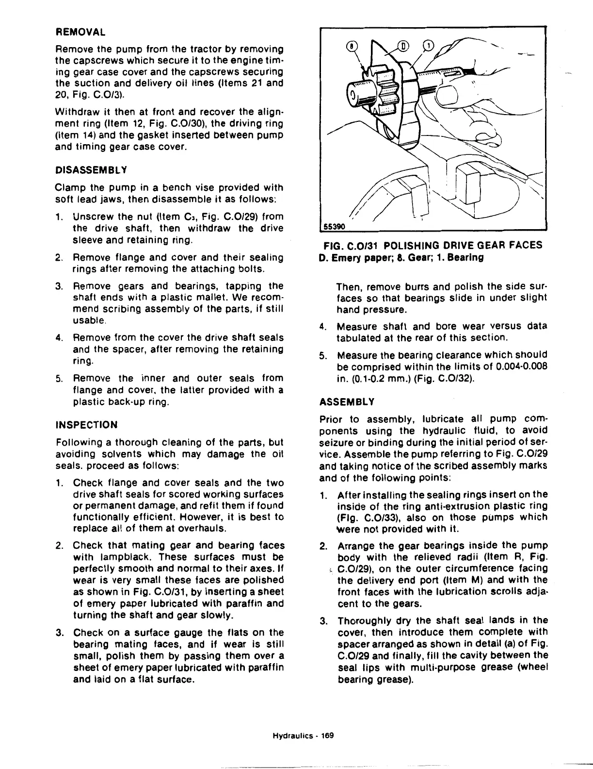
wear is very small these faces are polished
as shown in Fig. C.0/31, by
inserting
a sheet
of
emery paper lubricated
with
paraffin and
turning
the
shaft and gear slowly.
3.
Check on a surface gauge the
flats
on
the
bearing mating faces, and
if
wear is
still
small,
polish
them by passing
them
over a
sheet
of
emery paper lubricated
with
paraffin
and laid on a flat surface.
FIG. C.0/31 POLISHING DRIVE GEAR FACES
0.
Emery paper; 8. Gear; 1. Bearing
Then, remove burrs and polish the side sur·
faces so that bearings slide in under
slight
hand pressure.
4.
Measure shaft and bore wear versus data
tabulated at the rear
of
this
section.
5.
Measure the bearing clearance which should
be comprised
within
the
limits
of
0.004·0.008
in. (0.1·0.2 mm.) (Fig. C.0/32).
ASSEMBLY
Prior to assembly, lubricate all pump com-
ponents using
the
hydraulic fluid, to avoid
seizure or binding during the
initial
period
of
ser-
vice. Assemble the pump referring
to
Fig. C.0/29
and taking
notice
of
the scribed assembly marks
and
of
the
following
points:
1.
After
installing
the sealing rings insert on
the
inside
of
the ring anti-extrusion
plastic
ring
(Fig. C.0/33), also on those pumps
which
were
not
provided
with
it.
2.
Arrange
the
gear bearings
inside
the
pump
body
with
the relieved radii (Item
R,
Fig.
,.
C.0/29), on
the
outer
circumference facing
the
delivery end port (Item M) and
with
the
front faces
with
the lubrication
scrolls
adja-
cent
to
the gears.
3.
Thoroughly
dry
the shaft seal lands
in
the
cover, then introduce them complete
with
spacer arranged as shown in detail
(a)
of
Fig.
C.0/29 and finally,
fill
the cavity between the
seal
lips
with
multi-purpose grease (wheel
bearing grease).
Hydraulics
• 169

 Loading...
