'
A.l CRANKCASE-CYLINDER HEAD-OIL SUMP
For a general overall inspection
of
the crankcase
components, remove
~ngine
from tractor as in·
dicated on page
6.
CRANKCASE AND CYLINDER LINERS
The cast iron crankcase and cylinder
block
unit
construction
comprises the cylinder liner bores,
crankshaft main bearings, camshaft bearing
bores, and the valve tappet bores. Cylinder
liners,
of
the dry type, are inserted by cold press
fitting.
New liners
must
be bored
to
proper size
after
installation in engine bore. (See
"Fits
and
Tolerances-Torque Specifications-section.)
Class
identification
letters
are stamped on
the
crankcase
top
surface (Fig. A.l/1
),
in cor-
respondence ':lf each liner.
CHECKING AND CLEANING THE CRANKCASE
At overhauls check for causes of oil and water
leaks and seepage.
Proceed
as
follows:
1.
Wash the crankcase with a hot detergent and
water solution, and flush it repeatedly
with
cold water.
2.
Degrease the lubrication passages
with
a
jet
of pressurized air and solvent mixture and
remove sludge from the inside
of
passages.
3.
Check sealing
tightness
of
threaded and ex-
pansion plugs, and replace damaged ones.
4.
Check the face parallelism
of
the cylinder
head mating surface using a straight edge
and feeler gauge and,
if
necessary, reface it.
5.
To avoid fluid leaks or seepage, make sure
both crankcase and cylinder head mating
surfaces are clean, before installing the
gasket. Do not use any type
of
gasket
sealant.
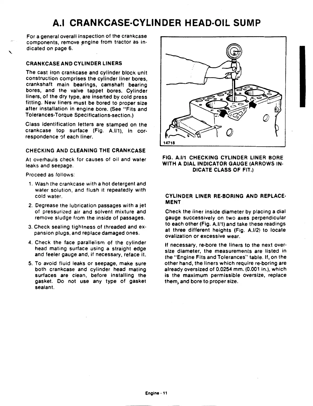
14718
FIG. A.l/1 CHECKING CYLINDER LINER BORE
WITH A DIAL INDICATOR GAUGE (ARROWS IN·
DICATE CLASS OF FIT.)
CYLINDER LINER RE-BORING AND REPLACE·
MENT
Check the
liner
inside diameter by placing a dial
gauge successively on
two
axes perpendicular
to
each other (Fig. A.l/1) and take these readings
at three
different
heights (Fig. A.l/2)
to
locate
ovalization
or
excessive wear.
If
necessary, re-bore
the
liners
to
the next over·
size diameter, the measurements are listed in
the
"Engine
Fits
and Tolerances" table. If, on the
other
hand, the liners
which
require re-boring are
already oversized
of
0.0254 mm.
(0.001
in.), which
is
the maximum permissible oversize, replace
them, and bore
to
proper size.
Engine·
11
 Loading...

