withdraw the driven shaft
(40,
Fig.
8.11/28)
and
ball bearing
(41)
rearwards as
an
assembly
acting on the front end
as
illustrated;
recover the gears and the synchromesh
device from the housing;
remove, at the press
if
necessary, the rear
roller bearing
(41)
from the shaft and the front
ball bearing
(43,
Fig~
8.11/30)
from the hous-
ing, the latter with the aid
of
a drive bar.
25027
25026
Jl. /
FIG.
8.11/28
REMOVING THE DRIVEN SHAFT
(40)
41. Rear roller bearing.
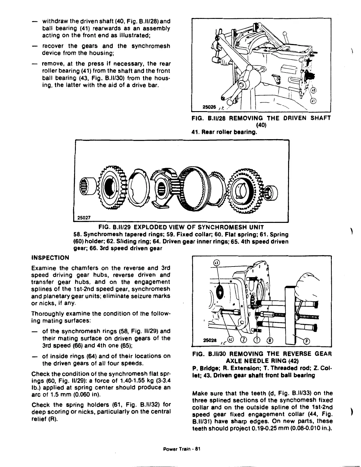
FIG.
8.11/29
EXPLODED VIEW OF SYNCHROMESH UNIT
58.
Synchromesh tapered rings;
59.
Fixed collar;
60.
Flat spring;
61.
Spring
(60)
holder;
62.
Sliding ring;
64.
Driven gear inner rings;
65.
4th speed driven
gear;
66.
3rd speed driven gear
INSPECTION
Examine the chamfers on the reverse and 3rd
speed driving gear hubs, reverse driven and
transfer gear hubs, and on the engagement
splines
of
the 1st-2nd speed gear, synchromesh
and planetary gear units; eliminate seizure marks
or
nicks,
if
any.
Thoroughly examine the condition
of
the follow-
ing mating surfaces:
of
the synchromesh rings
(58,
Fig.
11/29)
and
their mating surface on driven gears
of
the
3rd speed
(66)
and 4th one
(65);
of
inside rings
(64)
and
of
their
locations on
the driven gears
of
all four speeds.
Check the condition
of
the synchromesh flat spr-
ings
(60,
Fig.
11/29):
a force
of
1.40·1.55
kg
(3·3.4
lb.) applied at spring center should produce
an
arc
of
1.5 mm (0.060 in).
Check the spring holders
(61,
Fig.
8.11/32)
for
deep scoring
or
nicks, particularly on the central
relief
(R).
FIG.
8.11/30
REMOVING THE REVERSE GEAR
AXLE NEEDLE RING
(42)
P.
Bridge;
R.
Extension;
T.
Threaded rod;
Z.
Col·
let;
43.
Driven gear shaft front ball bearing
Make sure that the teeth
(d,
Fig.
8.11133)
on the
three splined
sections
of
the synchomesh fixed
collar
and on the
outside
spline
of
the 1st-2nd
speed gear fixed engagement collar
(44,
Fig.
8.11131)
have sharp edges. On new parts, these
teeth should project 0.19·0.25 mm (0.08·0.010 in.).
Power Train •
81
'
)
 Loading...

