10"
CLUTCH ADJUSTMENTS
The data necessary
for
the correct
adjustment
of
the
clutch
are noted by
the
letters
"A"
and
"B"
in
the
legend
of
Fig.
8.116.
The play A is set
with
the
clutch
installed on the
stand,
while
the play
B,
between the disengaging
sleeve
(12)
and levers
(11
),
is
featured by ad·
justing
the
free travel
of
the
control
pedal.
The
adjustments
made
with
the
clutch
installed
on the stand are, as
follows:
1.
To
adjust
the play (Item
A,
Fig.
8.116)
of
the
P.T.O.
clutch
release levers (Item
13),
install
the
clutch
without
the P.T.O.
clutch
disc
on
the universal stand (Item
0,
Fig.
8),
after
assembling
the spacer
bushings
(Item H) in
their
holes.
Insert the
clutch
centering
shaft
(Item
F),
6
speed
clutch
tool,
part no. 754246.
Secure the
clutch
to
the universal stand by
using the 3 threaded rods (Item
G,
Fig.
8.1/7)
which
are
tightened
up on the same line
with
the
outer
spacer bushings.
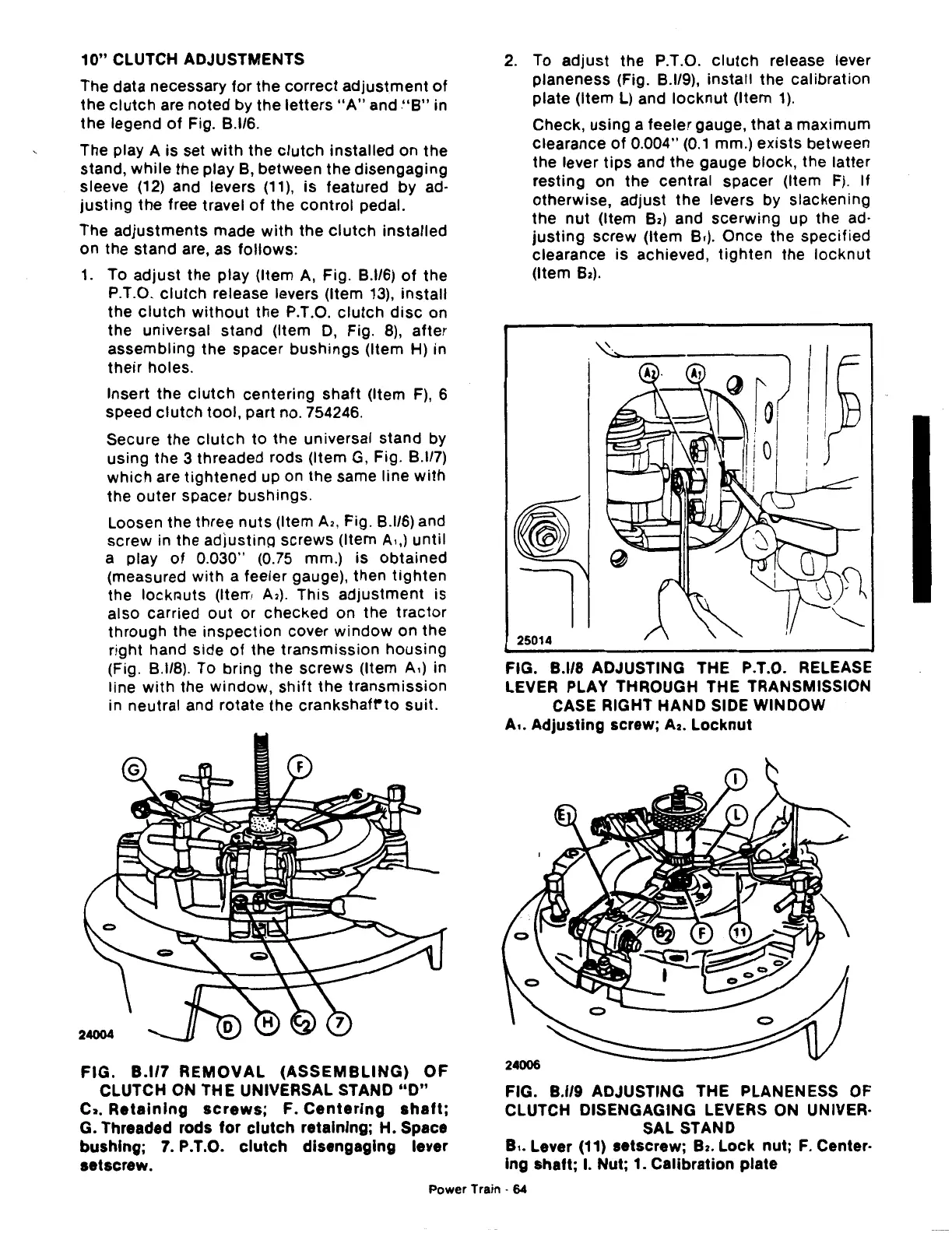
Loosen the three
nuts
(Item
A2,
Fig.
8.1/6)
and
screw in the adjustinQ screws (Item
A.,)
until
a play
of
0.030" (0.75 mm.) is
obtained
(measured
with
a feeler gauge), then
tighten
the
lockrwts
(Item
A2).
This
adjustment
is
also carried
out
or checked on the
tractor
through
the
inspection
cover
window
on the
right hand side
of
the
transmission
housing
(Fig.
8.118).
To bring the screws (Item A,) in
line
with
the window,
shift
the
transmission
in neutral and rotate the
crankshafrto
suit.
FIG.
8.117
REMOVAL
(ASSEMBLING)
OF
CLUTCH ON THE UNIVERSAL STAND
"D"
C2.
Retaining
screws;
F.
Centering
shaft;
G. Threaded rods
for
clutch
retaining; H. Space
bushing;
7.
P.T.O.
clutch
disengaging lever
setscrew.
2.
To
adjust
the P.T.O.
clutch
release lever
planeness (Fig.
8.1/9),
install the calibration
plate (Item
L)
and
locknut
(Item
1).
Check, using a feeler gauge, that a maximum
clearance
of
0.004"
(0.1
mm.)
exists
between
the lever
tips
and the gauge block, the latter
resting on the central spacer (Item
F).
If
otherwise,
adjust
the
levers by slackening
the
nut
(Item
Bz)
and
scerwing
up the ad·
justing
screw (Item B.). Once the
specified
clearance is achieved,
tighten
the
locknut
(Item
Bz).
"
....
I
25014
FIG. 8.1/8 ADJUSTING THE P.T.O. RELEASE
LEVER PLAY THROUGH THE TRANSMISSION
CASE RIGHT
HAND
SIDE WINDOW
A,.
Adjusting
screw;
A2.
Locknut
FIG. 8.1/9 ADJUSTING THE PLANENESS OF
CLUTCH DISENGAGING LEVERS ON UNIVER·
SAL STAND
8,.
Lever (11) setscrew; 82.
Lock
nut;
F.
Center·
lng
shaft; I. Nut; 1. Calibration plate
Power Train ·
64
 Loading...

