BEVEL GEAR SETTING
Adjustment
operations are grouped under the
following
subtitles:
1.
Adjusting
the
bevel gear
pinion
shaft tapered
roller
bearings and
finding
shim
thickness
(Item Sp, Fig.
8.11116).
Install
the
pinion
shaft
with
a
stack
of
shims
(Item
s,,
Fig.
8.11118)
of
any thickness, the
tapered roller bearings (Items
21
and 24)
previously lubricated, the P.T.O. driving gear
(Item
22) and
its
spacer (Item 23), then make
sure that the gear, the rear bearing cone, the
shim
and the
pinion
back end are all in con-
tact
with
each other.
Lubricate the
locknut
(Item
C3)
thread
with
crankcase oil and gradually
tighten
it
with
the
torque wrench F (Fig.
8.11119)
with
torque
increments
of
1.5 ft.-lbs.
(2
N•m)
up
to
the
value
of
7.2
ft.-lbs.
(10
N•m). Simultaneously,
turn the shaft a few turns
after
each torquing
step
to
make sure the tapered rollers are pro-
perly seated.
NOTE:
After
turning the shaft
following
the
final torquing step, re-check the torque and
reset
it
if
necessary.
Measure the clearance (Item L,, Fig.
8.111/8)
with
a feel gauge between P.T.O. driving gear
and spacer and select
two
adjustment
shims
(Item Sp, Fig.
8.11116)
the sum
of
which
is
equal to the value
of
the clearance previously
measured plus 0.002" (0.05 mm.).
NOTE: When selecting the
shims
(Item Sp),
measure each shim
with
a
micrometer
then
add the readings. Do not rely on a single
measurement
of
the stack
or
on the nominal
thickness
given for the individual shims.
2.
Checking the pinion cone center distance
and
finding
the correct
thickness
of
the shim
pack (Item
S,
Fig.
8.111/6).
Remove the bevel gear
pinion
shaft previous-
ly installed, install the reference shaft (Item
E,
Fig.
8.111/10),
insert the adjustments
shims
(Item Sp) found in paragraph 1 and then
block
the
stack by means
of
the knurled knob.
FIG.
B.llln
FITTING (REMOVING) THE DIF-
FERENTIAL BEARING HOUSINGS
NOTE: Arrow Indicates correct assembly posi·
tion
of
the
oil
drain hole.
Sd. Right hand side bearing shims;
6.
Right bear·
ing
housing bracket
~-------~~r==~~J~------~)
;
25286
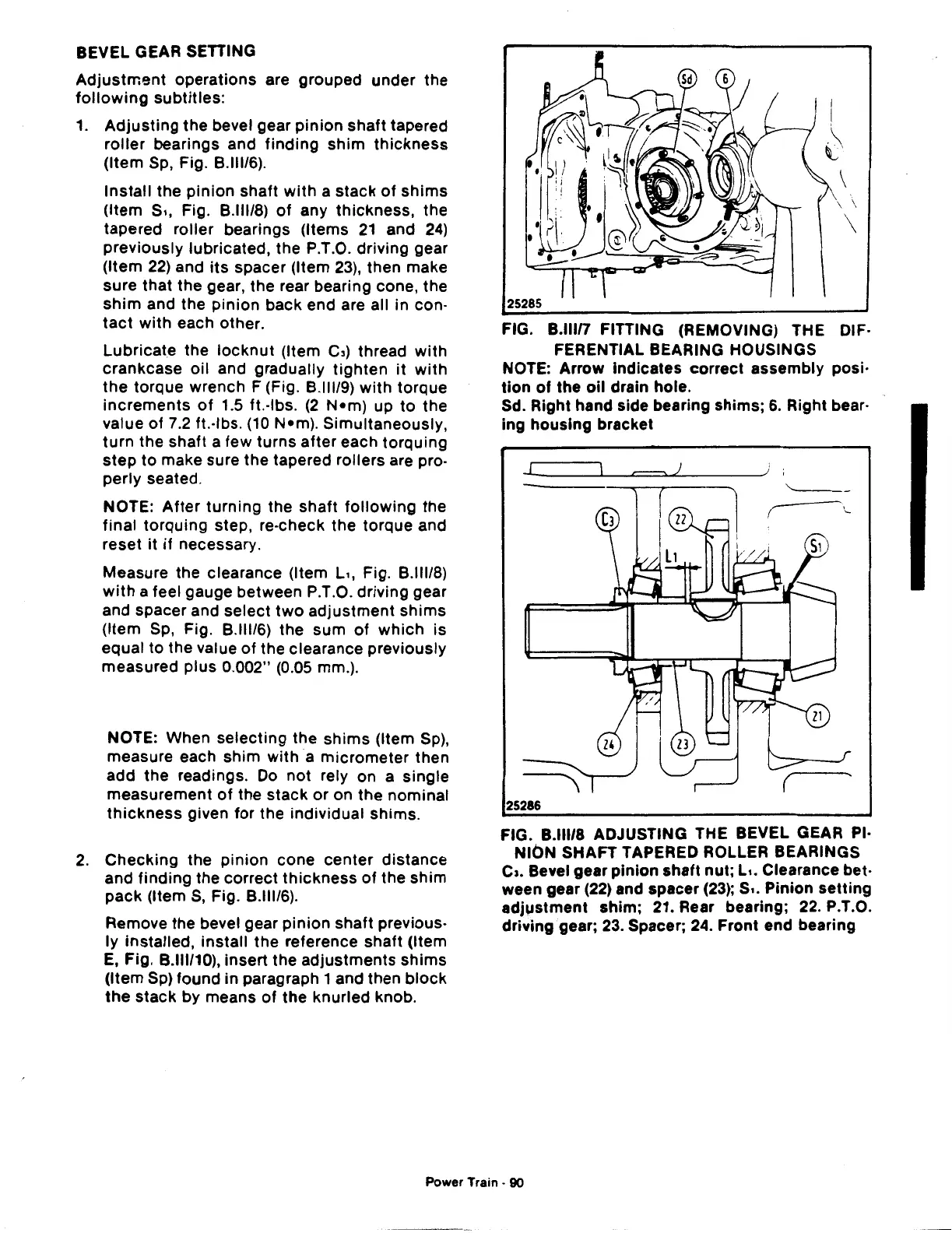
FIG. B.lll/8 ADJUSTING THE BEVEL GEAR PI·
NION SHAFT TAPERED ROLLER BEARINGS
c,.
Bevel gear pinion
shaft
nut; L
••
Clearance bet-
ween gear
(22) and spacer (23); s
..
Pinion setting
adjustment shim; 21. Rear bearing;
22.
P.T.O.
driving gear;
23. Spacer; 24. Front end bearing
Power Train -
90
 Loading...

