152040
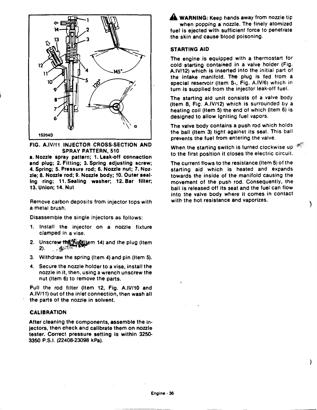
FIG. A.IV/11 INJECTOR CROSS-SECTION AND
SPRAY PATTERN, 510
a.
Nozzle spray pattern; 1. Leak-off
connection
and plug;
2.
Fitting;
3.
Spring
adjusting
screw;
4.
Spring;
5.
Pressure rod;
6.
Nozzle
nut;
7.
Noz·
zle;
8.
Nozzle rod;
9.
Nozzle body; 10.
Outer
seal·
lng
ring; 11. Sealing washer; 12. Bar
filter;
13. Union; 14.
Nut
Remove carbon
deposits
from
injector
tops
with
a metal brush.
Disassemble
the
single
injectors
as
follows:
1.
Install
the
injector
on
a nozzle
fixture
clamped in a vise.
2.
Unscre.w··t~m
14)
and the
plug
(Item
2).
A..-,'(!;,':''
'
..
~~
3.
Withdraw
the
spring (Item
4)
and
pin
(Item
5).
4.
Secure
the
nozzle
holder
to
a vise,
install
the
nozzle in it, then,
using
a
wrench
unscrew
the
nut
(Item
6)
to
remove
the
parts.
Pull the rod
filter
(Item 12, Fig. A.IV/10 and
A.IV/11)
out
of
the
inlet
connection,
then
wash all
the
parts
of
the
nozzle
in
solvent.
CALIBRATION
After
cleaning
the
components,
assemble
the
in·
jectors,
then
check
and
calibrate
them
on
nozzle
tester.
Correct
pressure
setting
is
within
3250·
3350 P.S.I. (22408-23098 kPa).
A WARNING: Keep hands away
from
nozzle
tip
when
popping
a nozzle. The
finely
atomized
fuel
is
ejected
with
sufficient
force
to
penetrate
the
skin
and cause 'blood
poisoning.
STARTING AID
The
engine
is
equipped
with
a
thermostart
for
cold
start~ng
contained
in
a valve
holder
(Fig.
A.IV/12)
which
is
inserted
into
the
initial
part
of
the
intake
manifold.
The
plug
is
fed from a
special
reservoir (Item
s.,
Fig. A.IV/6)
which
in
turn
is
supplied
from
the
injector
leak-off fuel.
The
starting
aid
unit
consists
of
a valve body
(Item 8, Fig. A.IV/12)
which
is
surrounded by a
heating
coil
(Item
5)
the end
of
which
(Item
6)
is
designed
to
allow
igniting
fuel vapors.
The valve body
contains
a push rod
which
holds
the
ball
(Item
3)
tight
against
its
seat. This ball
prevents
the
fuel
from
entering
the
valve.
When
the
starting
switch
is
turned
clockwise
up
1£t
.
to
the
first
position
it
closes
the
electric
circuit.
The
current
flows
to
the resistance (Item
5)
of
the
starting
aid
which
is heated and expands
towards
the
inside
of
the
manifold
causing
the
movement
of
the
push
rod. Consequently,
the
ball
is
released
off
its
seat and the fuel can
flow
into
the
valve
body
where
it
comes
in
contact
with
the
hot
resistance
and vaporizes.
Engine·
36
)
 Loading...

