Remove the
nut
shaft
complete
and in-
spect the
nut
examining
the
uniformity
of
the
contact
areas on the working surfaces.
To correct,
if
necessary,
suitably
vary
the
shim
stack
(Items,,
Fig. B.VIII/4)
considering
that
if
the stack
is
increased then the
shims
(Item
S),
found in paragraph 1
should
be cor-
respondingly increased and vice-versa.
NOTE: The aforementioned
adjustment
may
be used at steering box overhauls as a fur-
ther
check
of
the worm-and-nut setting,
if
the
parts are reusable. In
this
case we suggest
maintaining the original factory
shim
stack
(Item
s,,
Fig. B.VIII/4).
Alter
the shim
stack
only when one or more parts are replaced.
FRON.T
AXLE AND STEERING
DESCRIPTION
The front axle is
tubular
and
centrally
pivoted
and has
telescopic
beam
extensions
which
allow
a range
of
tread
width
adjustments.
By
moving the front axle beam
extensions
it is
possible
to
obtain the
following
different
tread
width
adjustments:
360C-40-52
in. (1016-1321 mm) 4
positions
360-50.77.5
in. (1280-1975 mm) 8
positions
460V-32.2-41.2 in. (843.3-1153.2 mm) 4
positions
460-50.3-77.5
in. (1280-1975 mm) 8
positions
510-50.3·77.5
in. (1280-1975 mm) 8
positions
OVERHAUL
If the front axle
trunnion
assembly requires ser-
vicing, proceed as
follows:
1.
Apply the hand brake and insert wooden
wedges
to
block
the drive wheels.
2.
At one axle end, remove
the
bolt
(Item c.,
Fig. B.VIII/7), the steering lever (Item
17)
from
the wheel spindle,
withdraw
the
pin (Item
18)
and loosen the
screws
(Item
Ca).
3.
Place a hydraulic
jack
under
the crankcase
oil
sump
and raise
the
front
end
of
the
tractor
to
take the
weight
off
the axle.
4.
Remove the
front
wheel, spindle-beam exten-
sion assembly (Item 19, Fig. B.VIII/7).
5.
Remove the
setscrew
(Item
C1,
Fig. B.VIII/8)
and
then
the
trunnion
pin (Item
20)
using
a
sliding
weight
type
puller
and adaptor.
6. Remove the front axle and
remaining
wheel
as an assembly and recover the end
thrust
washers (Item 25, Fig. B.VIII/9).
---
'85306
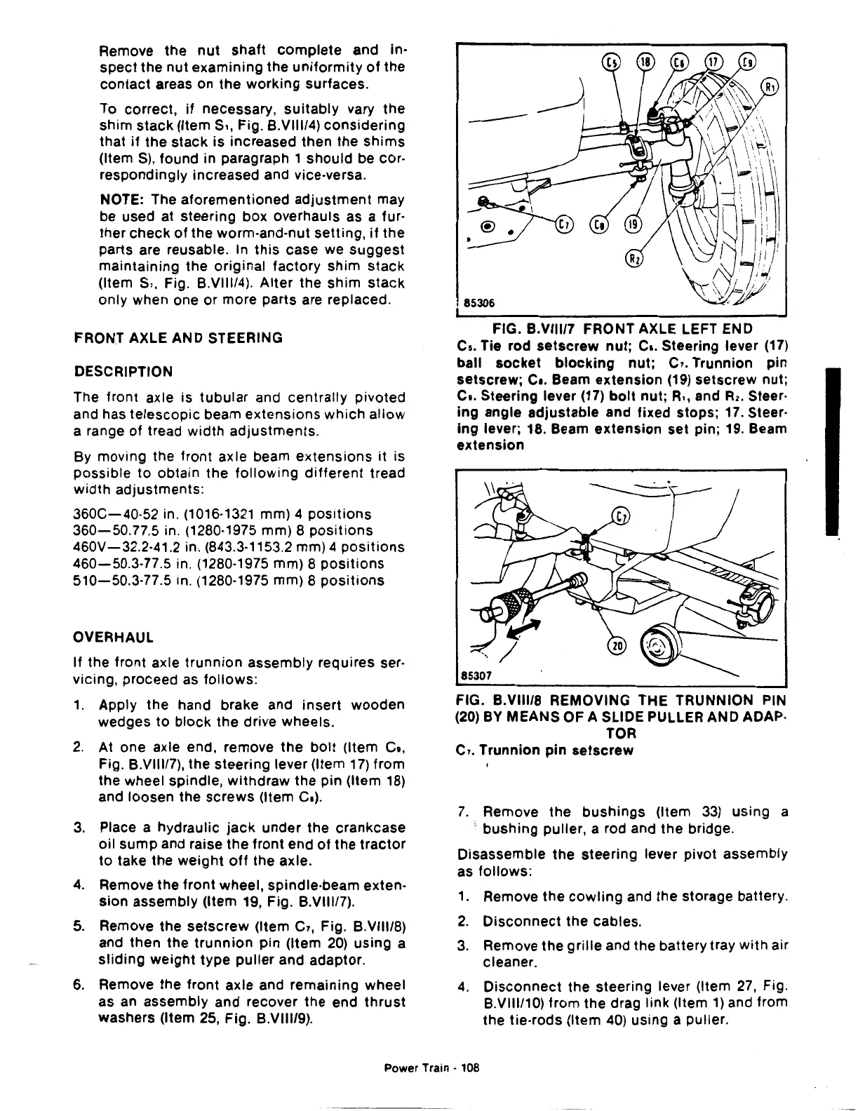
FIG. B.VIII/7 FRONT AXLE LEFT END
Cs.
Tie rod
setscrew
nut;
c
•.
Steering lever
(17)
ball
socket
blocking
nut;
c,. Trunnion pin
setscrew;
c
•.
Beam
extension
(19)
setscrew nut;
c
•.
Steering lever
(17)
bolt
nut; R,, and
R2.
Steer·
ing
angle adjustable and fixed stops; 17. Steer·
ing
lever; 18. Beam
extension
set pin; 19. Beam
extension
FIG. B.VIII/8 REMOVING THE TRUNNION PIN
(20)
BY
MEANS OF A SLIDE PULLER AND ADAP·
TOR
c,. Trunnion pin
setscrew
7.
Remove the
bushings
(Item
33)
using a
·.
bushing
puller, a rod and the bridge.
Disassemble the
steering
lever pivot assembly
as
follows:
1.
Remove
the
cowling
and the storage battery.
2.
Disconnect
the cables.
3.
Remove the
grille
and the battery tray
with
air
cleaner.
4.
Disconnect
the steering lever (Item
27,
Fig.
B.VIII/10)
from the drag link (Item
1)
and from
the tie-rods (Item
40)
using a puller.
Power Train · 108

 Loading...
