12.
Drain
the
lubricating
oil
from
the
differential
casing.
13.
Screw back the self-locking screws
(57)
and
remove the spherical bracket flange from the
differential
casing, recovering the steering
clamp
(Item
58,
Fig. B.IX/16) and
0-ring
bet-
ween the
two
flanges by
dismantling
the
spherical bracket (Item
26,
B.IX/10)
together
with
the
bushing
(25),
the oil ring
(24)
and the
bearing
outer
races
(27).
The tapered
roller
bearing
outer
races
of
the
joint
casing
should
be removed by the puller. When
necessary
to
replace the
bushing
(25)
and the oil
ring
(24)
use special tools.
14.
complete
removal
of
the
differential
drive pi-
nion (Item
P,
Fig. B.IX/12) from the differen-
tial
casing
is
carried
out
by
screwing
back
the
self-locking
screws (Item 55, Fig. B.IX/11)
and
dismantling
its
components
after
taking
out
the screws.
Be
careful when
withdrawing
the
oil
ring
(48)
the
screwdiver
to
be supported on the
outer
race, so
as
not
to
damage the sealing inner surface.
15.
the
two
outer
races
of
the tapered
roller
bear-
ing
(49
and
51)
and the inner race can be
removed from the support
(43)
and from the
differential
drive shaft
(45)
using
the univer-
sal puller.
16. by
withdrawing
the
right
joint
axis (Item
55,
Fig. B.IX/11) and
left
joint
axis
(17),
by screw-
ing
back the self-locking screws
(53),
the dif-
ferential
casing
should be
complete
separate
from
the
front
drive axle assembly. Recover
0-rings
(29 and
42).
17.
remove
the
differential
casing by
screwing
back the
screws
(54).
FIG. B.IX/8 WITHDRAWING THE BUSHINGS OF
THE
FRONT DRIVE AXLE SWINGING
SHAFT
A.
Elastic
bushing;
B.
Tensioner;
C.
Bride;
55.
Joint
axis, R.H.
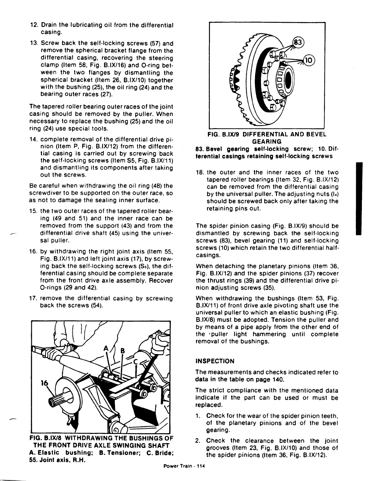
FIG. B.IX/9 DIFFERENTIAL AND BEVEL
GEARING
83. Bevel gearing
self-locking
screw; 10. Dif·
ferential
casings
retaining self-locking screws
18. the
outer
and the inner races
of
the
two
tapered roller bearings (Item
32,
Fig. B.IX/12)
can be removed from the
differential
casing
by the universal puller. The adjusting
nuts
(I•)
should
be screwed back only
after
taking
the
retaining pins out.
The spider
pinion
casing (Fig. B.IX/9) should be
dismantled
by
screwing
back the
self-locking
screws
(83),
bevel gearing
(11)
and self-locking
screws
(10)
which
retain the
two
differential
half-
casings.
When detaching the planetary
pinions
(Item 36,
Fig. B.IX/12) and the spider
pinions
(37)
recover
the
thrust
rings
(39)
and the
differential
drive pi-
nion adjusting screws
(35).
When
withdrawing
the
bushings
(Item
53,
Fig.
B.IX/11)
of
front
drive axle pivoting shaft use the
universal
pulleno
which
an elastic
bushing
(Fig.
B.IX/8)
must
be adopted. Tension the
puller
and
by means
of
a pipe apply from the
other
end
of
the •
puller
light
hammering
until
complete
removal
of
the bushings.
INSPECTION
The measurements and
checks
indicated refer
to
data
in
the
table on page 140.
The
strict
compliance
with
the
mentioned
data
indicate
if
the part can be used
or
must
be
replaced.
1.
Check
for
the wear
of
the spider
pinion
teeth,
of
the planetary
pinions
and
of
the bevel
gearing.
2.
Check the clearance between the
joint
grooves (Item
23,
Fig. B.IX/10) and those
of
the spider
pinions
(Item
36,
Fig. B.IX/12).
Power
Train·
114
 Loading...

