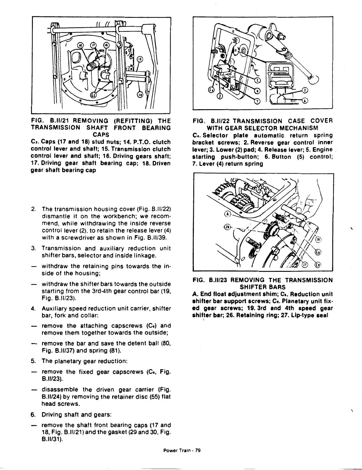
FIG. B.ll/21 REMOVING (REFITTING) THE
TRANSMISSION
SHAFT
FRONT BEARING
CAPS
C2.
Caps
(17
and 18)
stud
nuts;
14. P.T.O.
clutch
control
lever and shaft; 15. Transmission
clutch
control
lever and shaft; 16. Driving gears shaft;
17. Driving gear shaft bearing cap; 18. Driven
gear shaft bearing cap
2.
The
transmission
housing cover (Fig. B.ll/22)
dismantle it on the workbench; we recom·
mend, while withdrawing the
inside
reverse
control lever
(2),
to retain the release lever
(4)
with a screwdriver as shown in Fig. B.ll/39.
3.
Transmission and auxiliary reduction unit
shifter
bars,
selector
and inside linkage.
withdraw the retaining
pins
towards the in·
side
of
the housing;
withdraw
the
shifter
bars towards the
outside
starting from the 3rd·4th gear control bar
(19,
Fig.
8.11123).
4.
Auxiliary speed reduction unit carrier,
shifter
bar, fork and collar:
remove
the
attaching capscrews (Ce) and
remove
them
together
towards
the
outside;
remove
the
bar and save
the
detent ball
(80,
Fig. B.ll/37) and spring
(81).
5.
The planetary gear reduction:
remove
the
fixed gear capscrews (Ce, Fig.
8.11/23).
disassemble
the
driven gear carrier (Fig.
B.ll/24) by removing the retainer
disc
(55)
flat
head screws.
6.
Driving shaft and gears:
remove
the
shaft
front bearing caps
(17
and
18,
Fig.
8.11/21)
and the gasket
(29
and 30, Fig.
8.11/31).
FIG. B.ll/22 TRANSMISSION CASE COVER
WITH GEAR SELECTOR MECHANISM
c
•.
Selector
plate
automatic
return
spring
bracket screws;
2.
Reverse gear
control
inner
lever;
3.
Lower
(2)
pad;
4.
Release lever;
5.
Engine .
starting
push-button;
6.
Button
(5)
control;
7.
Lever
(4)
return spring
FIG. B.ll/23 REMOVING THE TRANSMISSION
SHIFTER BARS
A. End float
adjustment
shim;
Ca.
Reduction
unit
shifter
bar
support
screws; c
•.
Planetary
unit
fix·
ed
gear screws; 19. 3rd and 4th speed gear
shifter
bar;
26.
Retaining ring;
27.
Lip-type seal
I
Power Train ·
79
\
 Loading...

