~
I
~
1
I
X
I
2
I
I
' f
-
~
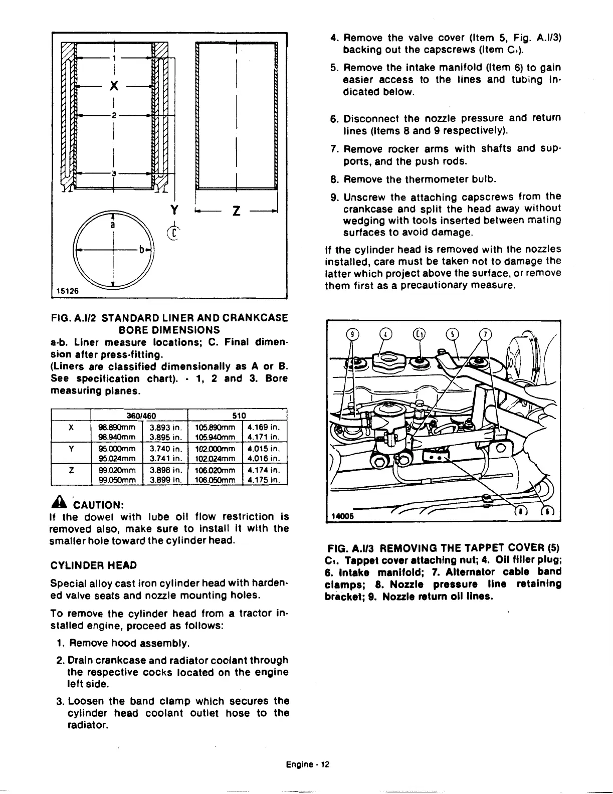
FIG. A.l/2 STANDARD LINER AND CRANKCASE
BORE DIMENSIONS
a-b. Liner measure locations;
C.
Final dimen·
sion after press-fitting.
(Liners are classified dimensionally as A
or
B.
See
specification chart). ·
1,
2 and
3.
Bore
measuring planes.
360/460
510
X
98.890mm 3.893 in. 105.890mm
4.169 in.
98.940mm 3.895 in. 105.940mm
4.171 in.
y
95.000mm 3.740 in. 102.000mm
4.015 in.
95.024mm 3.741 in. 102.024mm
4.016 in.
z
99.020mm 3.898 in.
106.020mm
4.174 in.
99.050mm 3.899 in.
106.050mm
4.175in.
A ·cAUTION:
If
the dowel
with
lube
oil
flow
restriction
is
removed also, make sure
to
install
it
with
the
smaller hole toward the
cylinder
head.
CYLINDER HEAD
Special alloy cast iron
cylinder
head
with
harden·
ed valve seats and nozzle mounting holes.
To remove the cylinder head from a tractor in·
stalled engine, proceed as follows:
1.
Remove hood assembly.
2.
Drain crankcase and radiator coolant through
the respective
cocks
located on the engine
left
side.
3.
Loosen
the
band
clamp
which secures the
cylinder head
coolant
outlet
hose
to
the
radiator.
4.
Remove the valve cover (Item
5,
Fig. A.l/3)
backing out the capscrews (Item C.).
5.
Remove the intake manifold (Item
6)
to gain
easier access
to
the lines and tubing in·
dicated below.
6. Disconnect the nozzle pressure and return
lines (Items 8 and 9 respectively).
7. Remove rocker arms
with
shafts and sup·
ports, and the push rods.
8. Remove the thermometer bulb.
9. Unscrew the attaching capscrews from the
crankcase and
split
the head away without
wedging with tools inserted between mating
surfaces
to
avoid damage.
If
the cylinder head is removed with the nozzles
installed, care must be taken not
to
damage the
latter which project above the surface, or remove
them first
as
a precautionary measure.
FIG. A.l/3 REMOVING THE TAPPET COVER
(5)
c,. Tappet cover attaching nut;
4.
011
filler plug;
6.
Intake manifold;
7.
Alternator cable band
clamps;
8. Nozzle pressure
line
retaining
bracket;
9.
Nozzle return
oil
lines.
Engine·
12
 Loading...

