25023
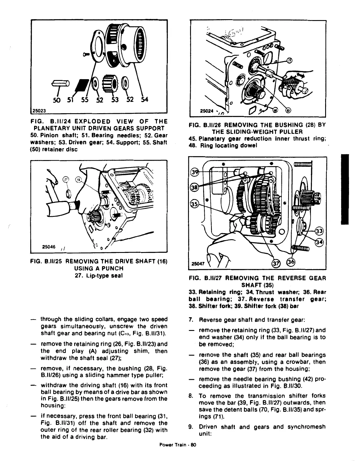
FIG.
B.ll/24
EXPLODED
VIEW
OF
THE
PLANETARY UNIT DRIVEN GEARS SUPPORT
50.
Pinion shaft;
51.
Bearing needles;
52.
Gear
washers;
53.
Driven gear;
54.
Support;
55.
Shaft
(50)
retainer
disc
25046 Jl
FIG. B.lll25 REMOVING THE DRIVE SHAFT
(16)
USING A PUNCH
27.
Lip-type seal
through the sliding collars, engage two speed
gears simultaneously, unscrew the driven
shaft gear and bearing nut (Cu, Fig.
8.11/31).
remove the retaining ring
(26,
Fig.
8.11123)
and
the end play
(A)
adjusting shim, then
withdraw the shaft seal
(27);
remove,
if
necessary, the bushing
(28,
Fig.
8.11126)
using a
sliding
hammer type puller;
withdraw the driving shaft
(16)
with
its
front
ball bearing by means
of
a drive bar as shown
in Fig.
8.11125)
then the gears remove from the
housing:
if
necessary, press the front ball bearing
(31,
Fig.
8.11131)
off
the shaft and remove the
outer
ring
of
the rear roller bearing
(32)
with
the aid
of
a driving bar.
FIG. B.lll26 REMOVING THE BUSHING
(28)
BY
THE SLIDING-WEIGHT PULLER
45. P.lanetary gear reduction inner thrust ring;
48.
Ring
locating
dowel
FIG. B.ll/27 REMOVING THE REVERSE GEAR
SHAFT
(35)
33.
Retaining ring; 34. Thrust washer; 36. Rear
ball
bearing;
37.
Reverse
transfer
gear;
38.
Shifter fork;
39.
Shifter
fork
(38)
bar
7.
Reverse gear shaft and transfer gear:
remove the retaining ring
(33,
Fig.
8.11127)
and
end washer
(34)
only
if
the ball bearing is
to
be removed;
remove the shaft
(35)
and rear ball bearings
(36)
as an assembly, using a crowbar, then
remove the gear
(37)
from the housing;
remove
the
needle bearing bushing
(42)
pro-
ceeding as illustrated in Fig.
8.11/30.
8.
To remove the transmission
shifter
forks
move the bar
(39,
Fig.
8.11/27)
outwards, then
save the detent balls
(70,
Fig.
8.11/35)
and spr-
ings
(71).
9.
Driven shaft and gears and synchromesh
unit:
Power
Train·
80

 Loading...
