15213
mm
19,940
19,960
In
.7850
.7858
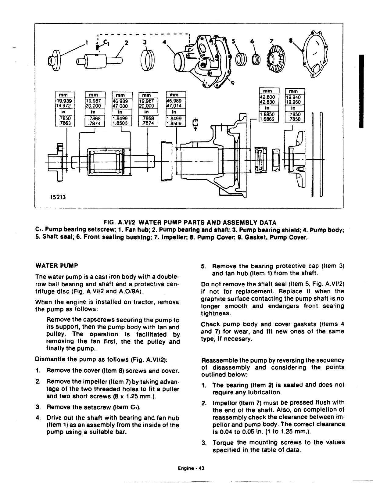
FIG. A.VI/2 WATER PUMP PARTS AND ASSEMBLY DATA
c
..
Pump bearing setscrew;
1.
Fan hub;
2.
Pump bearing and shaft;
3.
Pump bearing shield;
4.
Pump body;
5.
Shaft seal;
6.
Front sealing bushing;
7.
Impeller;
8.
Pump Cover;
9.
Gasket, Pump Cover.
WATER
PU'MP
The water pump is a cast iron body
with
a double·
row ball bearing and shaft and a protective cen·
trifuge
disc
(Fig. A.VI/2 and A.0/9A).
When the engine
is
installed on tractor, remove
the pump as follows:
Remove the capscrews securing the pump
to
its
support, then the pump body
with
fan and
pulley. The operation
is
facilitated
by
removing the fan first, the the pulley and
finally
the pump.
Dismantle the pump as
follows
(Fig. A.VI/2):
1.
Remove the cover (Item
8)
screws and cover.
2.
Remove the impeller (Item
7)
by taking advan·
tage
of
the
two
threaded holes
to
fit
a puller
and
two
short screws
(8
x 1.25 mm.).
3.
Remove the setscrew (Item C.).
4.
Drive
out
the shaft
with
bearing and fan hub
(Item
1)
as an assembly from the inside
of
the
pump using a suitable bar.
5.
Remove the bearing protective cap (Item
3)
and fan hub (Item
1)
from the shaft.
Do
not
remove the shaft seal (Item
5,
Fig. A.VI/2)
if
not for replacement. Replace
it
when the
graphite surface contacting the pump shaft is no
longer smooth and endangers front sealing
tightness.
Check pump body and cover gaskets (Items 4
and
7)
for
wear, and
fit
new ones
of
the same
type',
if
necesary.
Reassemble the pump by reversing the sequency
of
disassembly and considering the points
outlined
below:
1.
The bearing (Item
2)
is
sealed and does not
require any lubrication.
2.
lmpellor
(Item
7)
must
be pressed flush with
the end
of
the shaft. Also, on completion
of
reassembly check the clearance between im·
pellor
and pump body. The correct clearance
Is 0.04
to
0.05 in.
(1
to
1.25 mm.).
3.
Torque the
mounting
screws
to
the values
specified in the table
of
data.
Engine·
43
----
------------~
 Loading...

