ding
to
a
pull
scale reading
of
4.4
to
6.6 lbs.
(19.5
to
29.4
N).
This
rolling
torque can be
checked by
wounding
a cord around the
dif·
ferential housing and
connecting
it
to
a pull
scale. ·
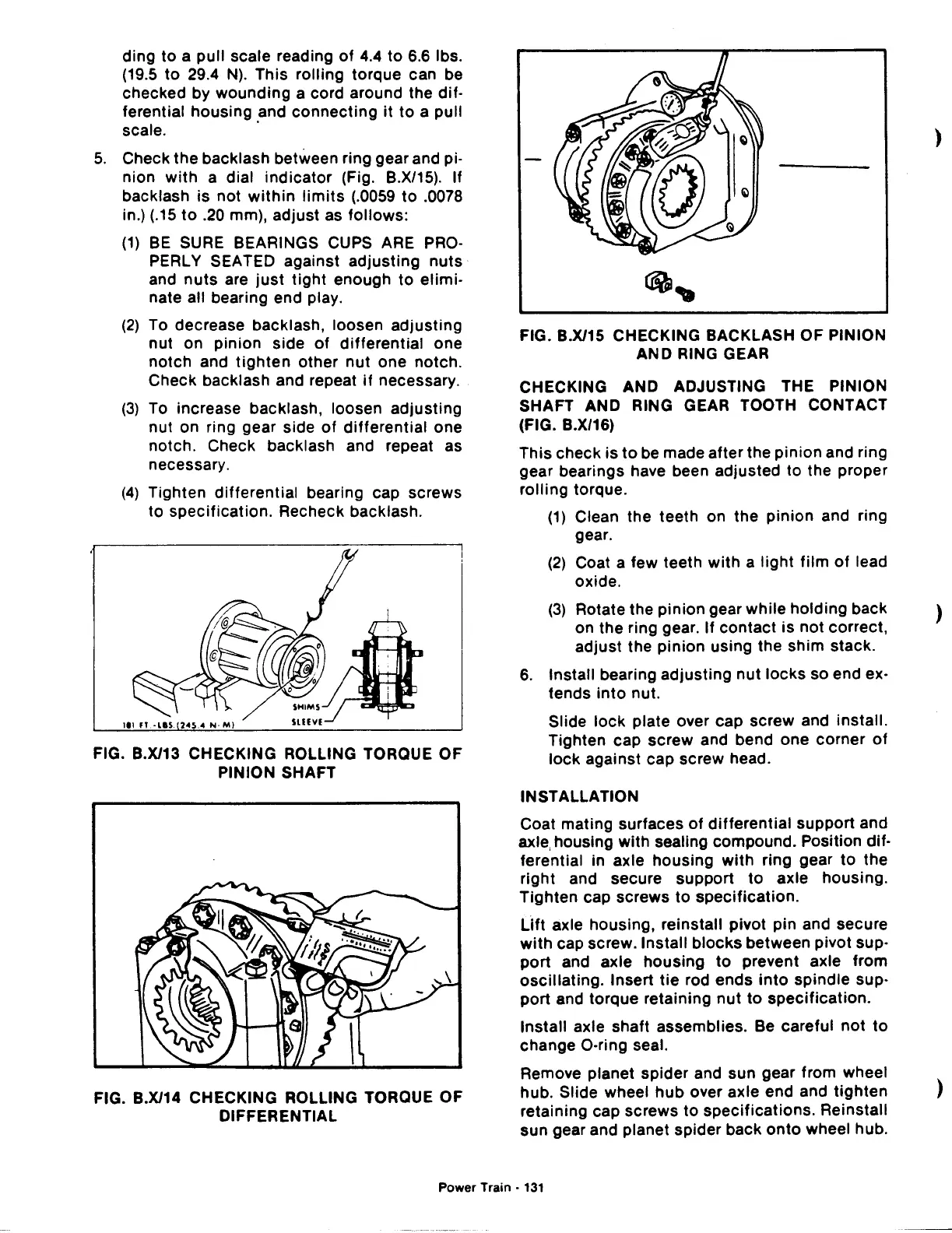
5.
Check
the
backlash between ring gear and pi-
nion
with
a dial
indicator
(Fig. B.X/15). If
backlash is not
within
limits
(.0059
to
.0078
in.) (.15
to
.20 mm), adjust as
follows:
(1)
BE
SURE BEARINGS CUPS ARE PRO·
PERL Y SEA TED against
adjusting
nuts
and
nuts
are
just
tight
enough
to
elimi-
nate all bearing end play.
(2)
To decrease backlash, loosen adjusting
nut on pinion side
of
differential
one
notch
and
tighten
other
nut
one notch.
Check backlash and repeat
if
necessary.
(3)
To increase backlash, loosen adjusting
nut on ring gear side
of
differential
one
notch. Check backlash and repeat as
necessary.
(4)
Tighten
differential
bearing cap screws
to specification. Recheck backlash.
FIG. B.X/13 CHECKING ROLLING TORQUE OF
PINION SHAFT
FIG. B.X/14 CHECKING ROLLING TORQUE
OF
DIFFERENTIAL
FIG. B.X/15 CHECKING BACKLASH OF PINION
AND RING GEAR
CHECKING AND ADJUSTING THE PINION
SHAFT AND RING GEAR TOOTH CONTACT
(FIG. B.X/16)
This check is
to
be made after the
pinion
and ring
gear bearings have been adjusted to the proper
rolling
torque.
(1)
Clean the teeth on the pinion and ring
gear.
(2)
Coat a few teeth
with
a
light
film
of
lead
oxide.
)
(3)
Rotate the
pinion
gear
while
holding back )
on the ring gear. If contact
is
not
correct,
adjust
the
pinion
using the shim stack.
6.
Install bearing adjusting
nut
locks
so end ex-
fends
into
nut.
Slide
lock
plate over cap screw and
install.
Tighten cap screw and bend one corner
of
lock
against cap screw head.
INSTALLATION
Coat mating surfaces
of
differential
support and
axle, housing with sealing compound. Position
dif·
ferential in axle housing
with
ring gear
to
the
right
and secure support
to
axle housing.
Tighten
cap screws
to
specification.
Lift
axle housing, reinstall pivot
pin
and secure
with
cap screw. Install
blocks
between pivot sup·
port
and axle
housing
to
prevent axle from
oscillating.
Insert
tie
rod ends
into
spindle sup-
port and torque retaining
nut
to
specification.
Install axle shaft assemblies. Be careful
not
to
change O·ring seal.
Remove planet spider and sun gear from wheel
hub. Slide wheel
hub
over axle end and
tighten
retaining cap screws
to
specifications.
Reinstall
sun gear and planet spider back
onto
wheel hub.
)
Power Train •
131
 Loading...

