install,
with
the
aid
of
grease,
the
gasket on
the
housing, then
install
the cover assembly,
making sure
that
the
ends
of
the hand con-
trol levers and
the
pad
(3,
Fig.
8.11/22)
of
the
inside
reverse
control
lever
fit
the selectors
(23
and 25, Fig.
8.11/38)
and the transfer gear
(37, Fig.
8.11/27)
respectively.
10.
Transmission and P.T.O.
clutch
release col-
lars and shifter, forks:
re-connect the grease line
(9,
Fig.
8.11/20)
to
the housing;
tighten
the cap screws
(Cu)
to the specified
torque value and wire
lock
them;
re-connect
the
link
(8,
Fig.
8.11/19)
to
the
P.T.O.
clutch
hand
control
lever.
TRANSMISSION INSTALLATION
Reserve the removal sequence and;
re-attach the
transmission
housing installing
the gasket;
make sure the
0-rings
(84,
Fig.
8.11/31)
have
been installed before attaching the end
(83)
of
the hydraulic
lift
pump suction line;
be
sure to meet torque requirements given in
the data table.
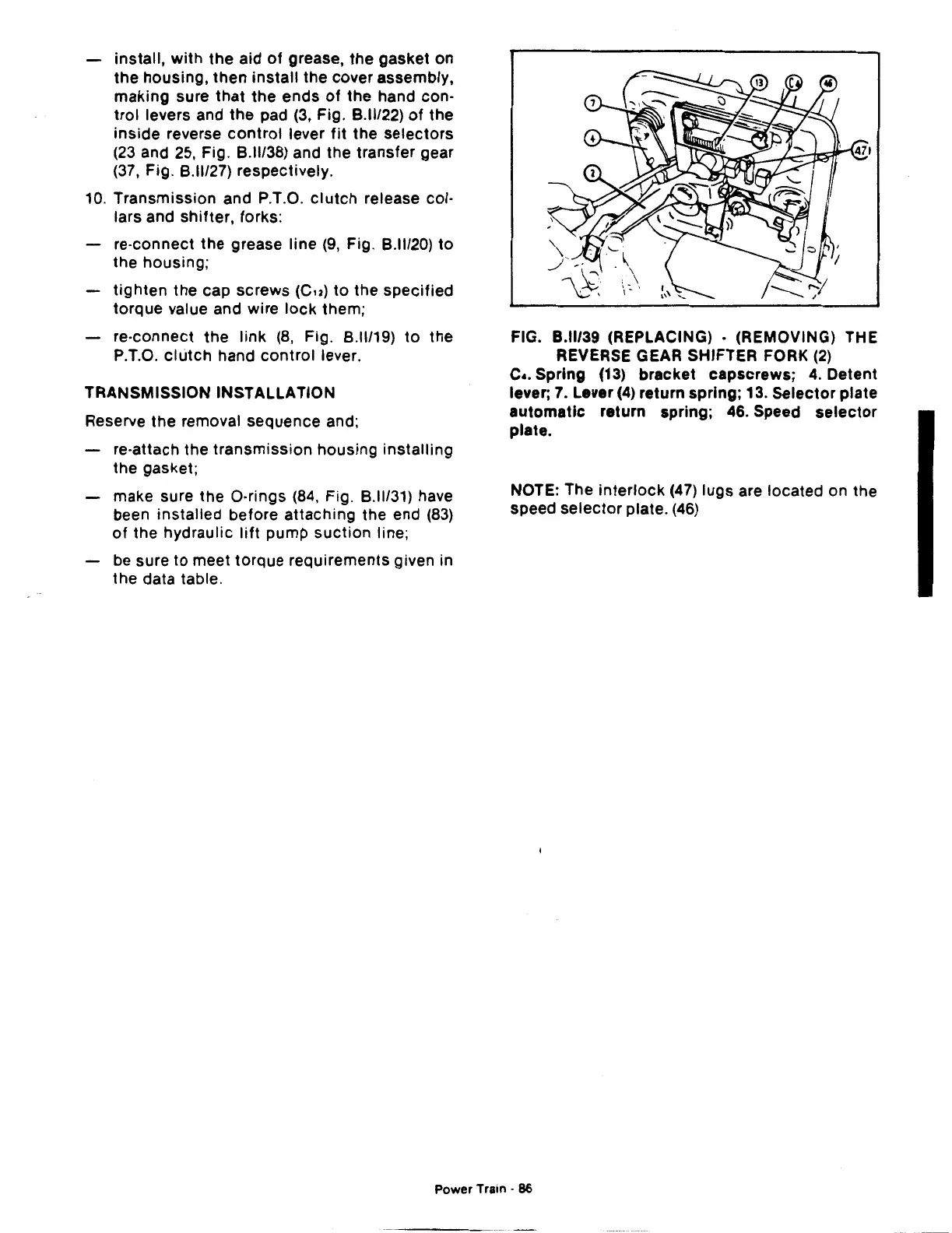
FIG. B.ll/39 (REPLACING) • (REMOVING) THE
REVERSE GEAR SHIFTER FORK
(2)
c
•.
Spring (13) bracket capscrews;
4.
Detent
lever; 7. Lever
(4)
return spring; 13. Selector plate
automatic
return spring; 46. Speed
selector
plate.
NOTE: The
interlock
(47)
lugs are located on the
speed
selector
plate.
(46)
Power Train ·
86
 Loading...

