C.l POWER STEERING (POWER ASSISTED)
INTRODUCTION
The
power
steering
system
comprises
the
following
main parts: (Fig. C.l/1)
1. The
oil
reservoir (Item
16)
containing
the
filter
with
replaceable element.
2.
The hydraulic
pump
(Item
8)
driven by the
engine
timing
gear.
3.
The pressure valve, incorporated in the
hydraulic pump,
allows
the steering
of
the
tractor
when the
pump
is
inoperative or the
engine has stopped, and regulates the
pressure.
4.
The operating
cylinder
with
double-acting
ram (Item
7)
and
built-in
control
valve, install·
ed in parallel
with
drag link.
5.
Oil pipes and hoses
connecting
the pump
to
the
cylinder
circuit.
There are
two
different
versions of the power
steering cylinder. Cylinder assemblies are inter-
changeable, but
components
are not.
OPERATION (UTB)
Oil
drawn from independent reservoir, position-
ed above engine, is transferred under pressure
to
cylinder
inlet
port. Force inacted upon steering
wheel
during
turn
is
directed
to
control
valve
spool.
Spool movement
allows
pressure upon
cylinder
piston
aiding
direction
of
turn.
1. NEUTRAL POSITION (A, FIG. C.l/2)
When ball
stud
is
subjected
to
side pressure
lower
than preload of reaction spring, control
valve remains on a
floating
balanced
position
between
shoulders
of
valve spool
(41)
because
of
force
exercised
by springs
(30)
and
(36).
In
this
condition,
ports
(I)
and
(L)
are open
allowing
free
flow
of
fluid.
Oil
delivered by
pump
will
flow
back
into
oil
reservoir
through
cylinder
chambers
(E)
and (F) and line
(40).
2. RETRACTED
POSITION-LEFT
TURN
(8,
FIG. C.l/2)
If
front
ball
stud
(17)
is
subjected
to
a force ac-
ting
on
piston
(43)
and exceeding preloading
of
reaction
spring
(30),
control
valve spool moves in
same
direction
with
respect
to
cylinder
rod
(9);
this
will
restrict
and,
if
load is at
maximum
inten-
sity,
it
will
shut
off
oil
flow
through
port
(I);
con-
sequently, pressure exercised by oil in
minor
chamber
(E)
increases and forces
piston
(43)
to
retract
cylinder
rod
(9).
Oil contained in
opposite
chamber
(H)
flows
freely
into
reservoir through
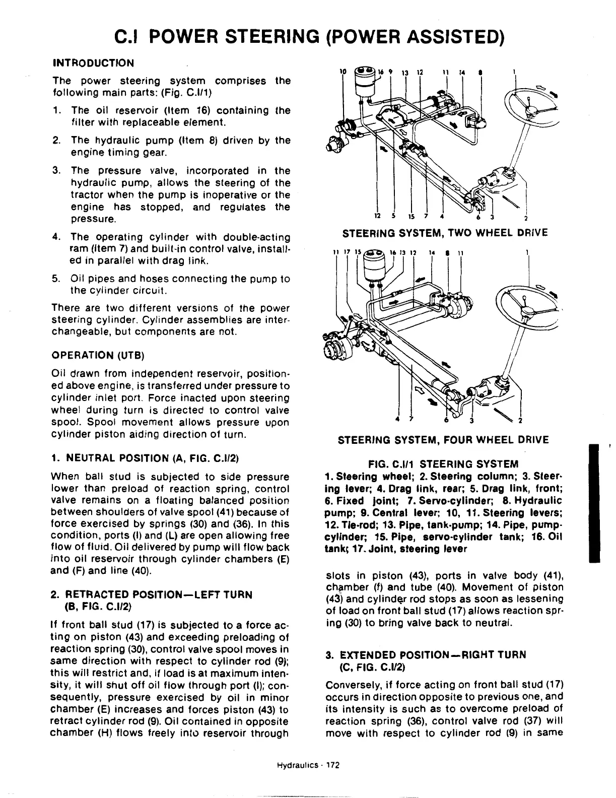
STEERING SYSTEM, TWO WHEEL DRIVE
STEERING SYSTEM, FOUR WHEEL DRIVE
FIG. C.l/1 STEERING SYSTEM
1. Steering wheel; 2. Steering
column;
3.
Steer·
lng
lever; 4. Drag
link,
rear;
5.
Drag link,
front;
6.
Fixed
joint;
7.
Servo·cylinder;
8.
Hydraulic
pump;
9. Central lever; 10, 11. Steering levers;
12. Tle·rod; 13. Pipe, tank·pump; 14. Pipe, pump-
cylinder;
15. Pipe, servo·cylinder tank; 16. Oil
tank\ 17.
Joint,
steering lever
slots
in
piston
(43),
ports
in valve body
(41),
chamber (f) and
tube
(40).
Movement
of
piston
(43) and cylindQ.r rod
stops
as soon as lessening
of
load on
front
ball
stud
(17)
allows
reaction spr-
ing
(30)
to
bring valve
back
to
neutral.
3.
EXTENDED
POSITION-RIGHT
TURN
(C, FIG. C.l/2)
Conversely,
if
force
acting
on
front
ball stud
(17)
occurs
in
direction
opposite
to
previous one, and
its
intensity
is
such
as
to
overcome preload
of
reaction spring
(36),
control
valve rod
(37)
will
move
with
respect
to
cylinder
rod
(9)
in same
Hydraulics
· 172

 Loading...
