55362
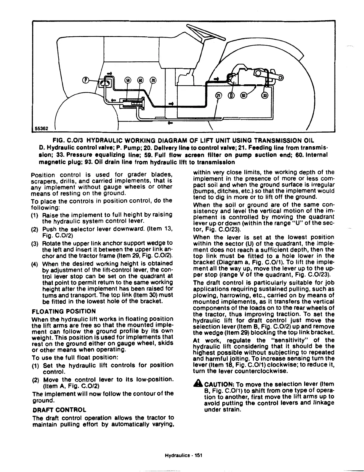
FIG. C.0/3 HYDRAULIC WORKING DIAGRAM OF LIFT UNIT USING TRANSMISSION OIL
D.
Hydraulic control valve;
P.
Pump;
20.
Delivery
line
to control valve;
21.
Feeding line from transmis·
sion;
33.
Pressure equalizing line;
59.
Full
flow
screen
filter
on pump suction end;
60.
Internal
magnetic plug;
93.
Oil drain line from hydraulic
lift
to transmission
Position control is used for grader blades,
scrapers, drills, and carried implements, that is
any implement
without
gauge wheels or other
means
of
resting on the ground.
To place the controls in position control, do the
following:
(1)
Raise the implement
to
full height by raising
the hydraulic system control lever.
(2)
Push the selector lever downward. (Item
13,
Fig. C.0/2)
(3)
Rotate the upper link anchor support wedge to
the left and insert it between the upper link
an·
chor and the tractor frame (Item
29,
Fig. C.0/2).
(4)
When
the desired working height is obtained
by adjustment
of
the lift-control lever, the con·
trol lever stop can
be
set
on
the quadrant at
that point
to
permit return to the same working
height after the implement has been raised for
turns and transport. The top link (Item
30)
must
be
fitted in the lowest hole of the bracket.
FLOATING POSITION
When the hydraulic
lift
works in floating position
the
lift
arms are free so that the mounted imple·
ment can
follow
the ground profile by Its own
weight. This
position
is used
for
implements that
rest on the ground either on gauge wheel, skids
or
other means when operating.
To use the full float position:
(1)
Set the hydraulic
lift
controls
for
position
control.
(2)
Move the control lever
to
Its low-position.
(Item
A,
Fig. C.0/2)
The Implement
will
now
follow
the contour
of
the
ground.
DRAFT CONTROL
The draft control operation allows the tractor to
maintain pulling effort by automatically varying,
within very close limits, the working depth
of
the
implement in the presence
of
more or less com·
pact soil and when the ground surface is irregular
(bumps, ditches, etc.) so that the implement would
tend to dig in more or to lift off the ground.
When the soil
or
ground are
of
the same con-
sistency and level the vertical motion
of
the im·
plement is controlled by moving the quadrant
lever up
or
down (within the range
"U"
of
the sec·
tor, Fig. C.0/23).
When the lever Is set at the lowest position
within
the sector
(U)
of
the quadrant, the imple·
ment does not reach a
sufficient
depth, then the
top
link
must
be
fitted
to
a hole lower in the
bracket (Diagram
a,
Fig. C.0/1). To
lift
the imple·
ment all the way up, move the lever up
to
the up·
per stop (range V
of
the quadrant, Fig. C.0/23).
The draft control is particularly suitable for job
applications requiring sustained pulling, such
as
plowing, harrowing, etc., carried on by means
of
mounted implements, as
it
transfers the vertical
components
of
the loads on to the rear wheels
of
the tractor, thus improving traction. To set the
hydraulic
lift
for
draft
control just move the
selection lever (Item
B,
Fig. C.0/2) up and remove
the wedge (Item
29)
blocking the
top
link
bracket.
At
work, regulate the
"sensitivity"
of
the
hydraulic
lift
considering that
it
should be the
highest possible
without
subjecting to repeated
and harmful jolting. To increase sensing turn the
lever (Item
18,
Fig. C.0/1) clockwise; to reduce it,
turn the lever counterclockwise.
A CAUTION: To move the selection lever (Item
B,
Fig. C.0/1)
to
shift
from one type
of
opera·
tion
to
another, first move the
lift
arms up to
avoid putting
the
control levers and linkage
under strain.
Hydraulics •
151
 Loading...

