FIG.
8.11/31
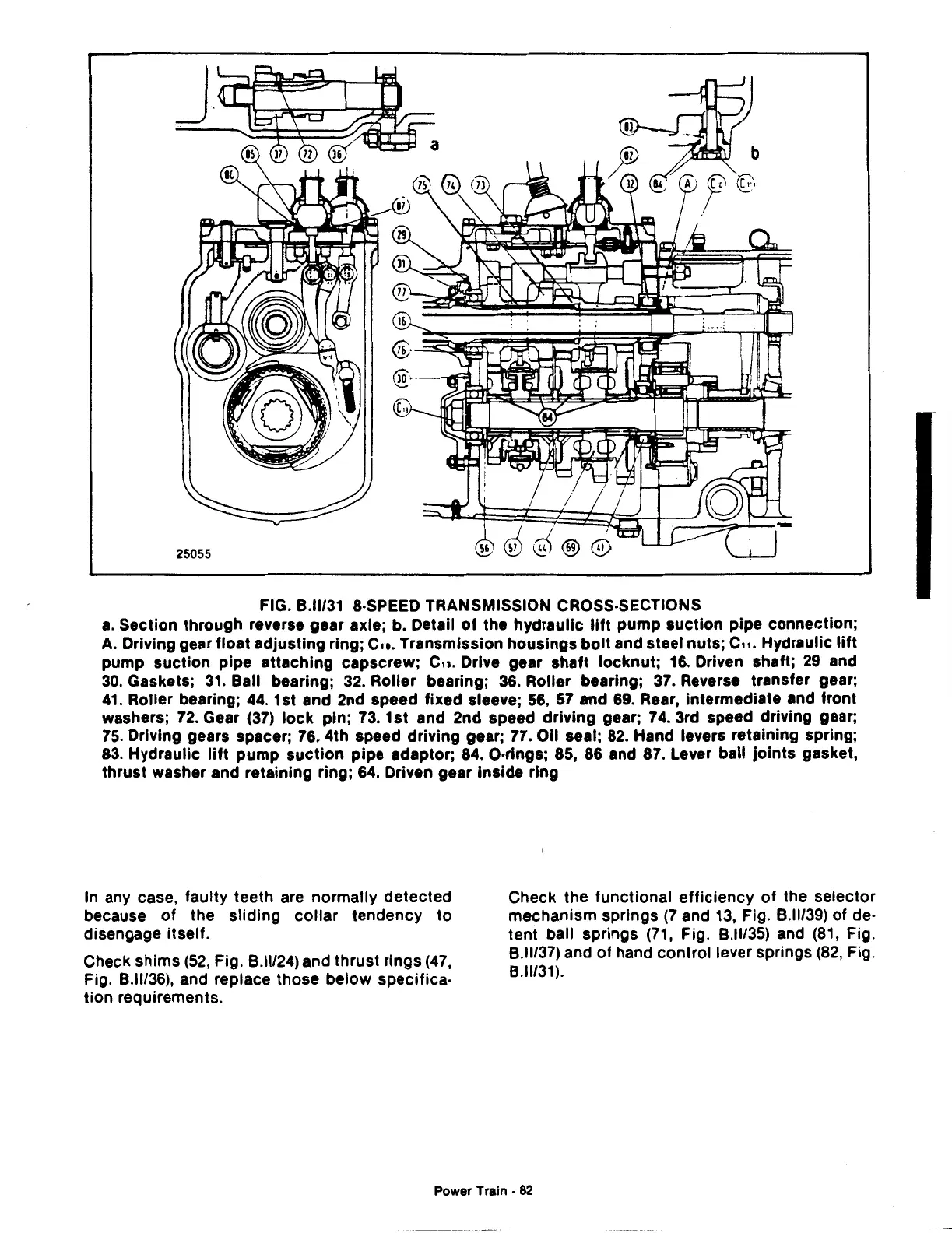
&·SPEED TRANSMISSION CROSS·SECTIONS
a.
Section through reverse gear axle; b. Detail
of
the hydraulic
lift
pump suction pipe connection;
A.
Driving gear float adjusting ring;
C1o.
Transmission housings
bolt
and steel nuts;
C11.
Hydraulic
lift
pump suction pipe attaching capscrew;
Cu.
Drive gear shaft locknut; 16. Driven shaft;
29
and
30.
Gaskets;
31.
Ball bearing;
32.
Roller bearing;
36.
Roller bearing;
37.
Reverse transfer gear;
41.
Roller bearing;
44.
1st and 2nd speed fixed sleeve;
56,
57
and
69.
Rear, intermediate and front
washers;
72.
Gear
(37)
lock
pin; 73. 1st and 2nd speed driving gear; 74. 3rd speed driving gear;
75.
Driving gears spacer; 76. 4th speed driving gear; 77. Oil seal;
82.
Hand levers retaining spring;
83.
Hydraulic
lift
pump
suction
pipe adaptor; 84. O·rings; 85, 86 and 87. Lever ball joints gasket,
thrust washer and retaining ring;
64.
Driven gear Inside ring
In
any case, faulty teeth are normally detected
because
of
the
sliding
collar
tendency
to
disengage itself.
Check shims
(52,
Fig.
8.11124)
and thrust rings
(47,
Fig.
8.11/36),
and replace those below specifica·
tion requirements.
Check the functional
efficiency
of
the selector
mechanism springs
(7
and
13,
Fig.
8.11139)
of
de·
tent ball springs
(71,
Fig.
8.11/35)
and
(81,
Fig.
8.11137)
and
of
hand control lever springs
(82,
Fig.
8.11131).
Power Train •
82
 Loading...

