-IY
-IY
85310/85308
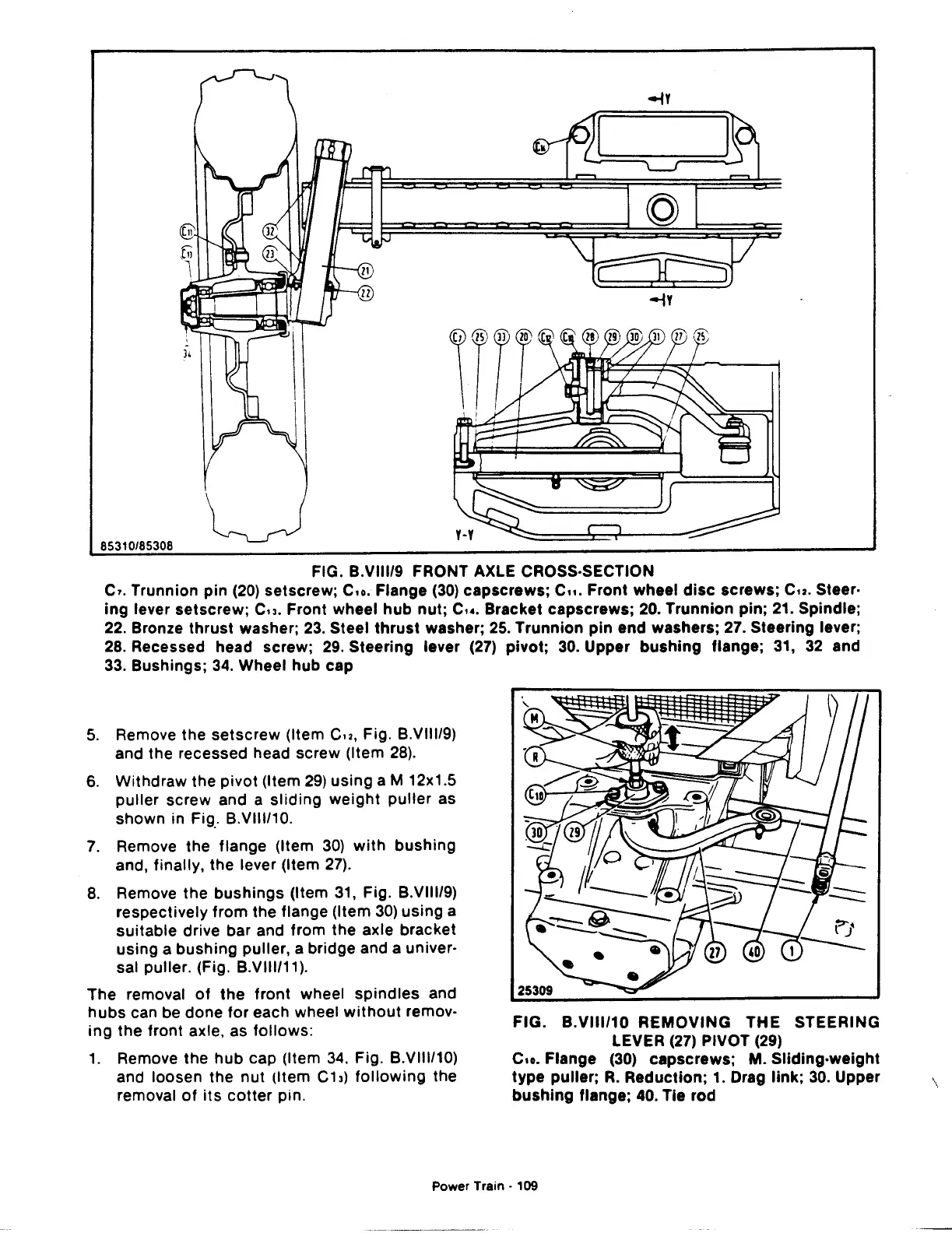
FIG. B.VIII/9 FRONT AXLE CROSS-SECTION
c,. Trunnion pin
(20)
setscrew;
Cu.
Flange
(30)
capscrews;
C11.
Front wheel
disc
screws;
Cu.
Steer·
ing
lever setscrew; Cu. Front wheel
hub
nut;
c,
•.
Bracket capscrews; 20. Trunnion
pin;
21. Spindle;
22. Bronze
thrust
washer;
23.
Steel
thrust
washer; 25. Trunnion
pin
end washers; 27. Steering lever;
28. Recessed head screw;
29.
Steering lever (27)
pivot;
30.
Upper
bushing
flange;
31,
32
and
33. Bushings;
34.
Wheel hub cap
5.
Remove the
setscrew
(Item
Cu,
Fig. B.VIII/9)
and the recessed head screw (Item
28).
6.
Withdraw the
pivot
(Item
29)
using
aM
12x1.5
puller
screw and a
sliding
weight
puller
as
shown in
Fig_.
B.VIII/10.
7.
Remove the flange (Item 30)
with
bushing
and, finally, the lever (Item
27).
8.
Remove the
bushings
(Item 31, Fig. B.VIII/9)
respectively
from
the flange (Item
30)
using
a
suitable
drive bar and from the axle bracket
using a
bushing
puller, a bridge and a univer·
sal puller. (Fig. B.VIII/11).
The
removal
of
the
front
wheel
spindles
and
hubs
can be done
for
each wheel
without
remov·
ing
the front axle, as
follows:
1.
Remove the
hub
cap (Item
34.
Fig. B.VIII/10)
and loosen the
nut
(Item C13)
following
the
removal
of
its
cotter
pin.
FIG.
B.VIII/10
REMOVING
THE
STEERING
LEVER
(27)
PIVOT (29)
C1o.
Flange (30) capscrews; M. Sliding-weight
type
puller;
R.
Reduction; 1. Drag
link;
30.
Upper
bushing
flange; 40. Tie rod
Power
Train·
109
\

 Loading...
