B
80
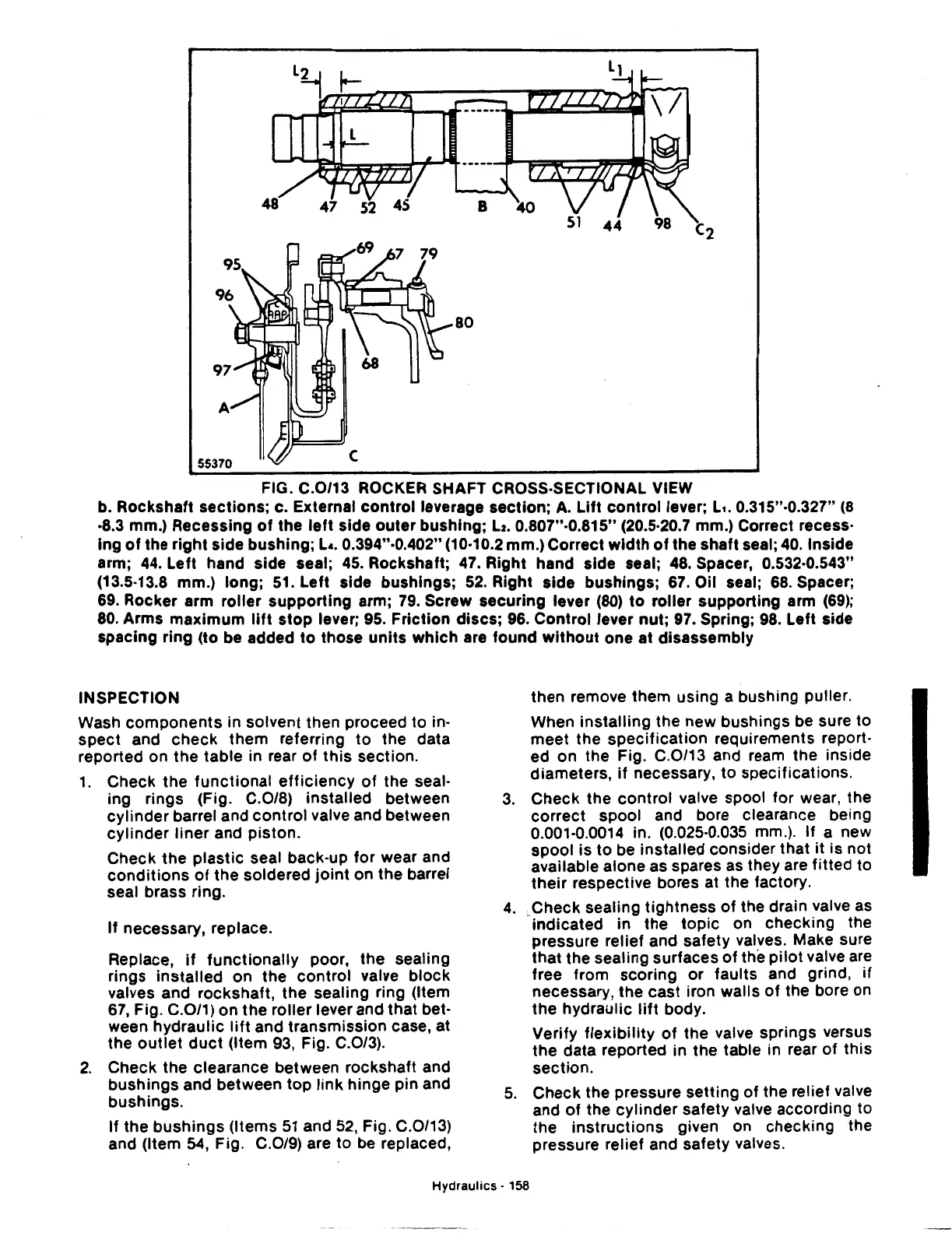
FIG. C.0/13 ROCKER SHAFT CROSS-SECTIONAL VIEW
b. Rockshaft sections; c. External
control
leverage section;
A.
Lift
control
lever; L
•.
0.315"·0.327"
(8
·8.3 mm.) Recessing
of
the
left
side
outer
bushing;
Lz.
0.807"·0.815" (20.5·20.7 mm.) Correct recess·
ing
of
the
right
side bushing; L •. 0.394"·0.402" (10·10.2 mm.) Correct
width
of
the shaft seal;
40.
Inside
arm; 44. Left hand side seal;
45.
Rockshaft; 47. Right hand side seal; 48. Spacer, 0.532·0.543"
(13.5·13.8 mm.)
long;
51.
Left
side bushings;
52.
Right side bushings; 67. Oil seal; 68. Spacer;
69. Rocker arm
roller
supporting
arm; 79. Screw securing lever (80)
to
roller supporting arm
(69);
80. Arms
maximum
lift
stop
lever; 95.
Friction
discs;
96.
Control
lever nut; 97. Spring; 98. Left side
spacing ring (to be added
to
those
units
which
are found
without
one at disassembly
INSPECTION
Wash
components
in solvent then proceed
to
in-
spect
and
check
them
referring
to
the data
reported on
the
table in rear
of
this
section.
1.
Check
the
functional
efficiency
of
the seal-
ing rings (Fig. C.0/8) installed between
cylinder
barrel and
control
valve and between
cylinder
liner
and
piston.
Check
the
plastic
seal back-up
for
wear and
conditions
of
the
soldered
joint
on
the
barrel
seal brass ring.
If
necessary, replace.
Replace,
if
functionally
poor,
the
sealing
rings
installed
on
the
control
valve
block
valves and rockshaft,
the
sealing ring (Item
67, Fig. C.0/1)
on
the
roller
lever and
that
bet-
ween
hydraulic
lift
and
transmission
case, at
the
outlet
duct
(Item 93, Fig. C.0/3).
2.
Check
the
clearance between rockshaft and
bushings
and between
top
link
hinge pin and
bushings.
If
the
bushings
(Items
51
and
52,
Fig. C.0/13)
and (Item
54,
Fig. C.0/9) are
to
be replaced,
then
remove them using a bushing puller.
When
installing
the
new bushings be sure
to
meet
the
specification
requirements report-
ed on the Fig. C.0/13 and ream
the
inside
diameters,
if
necessary,
to
specifications.
3.
Check
the
control
valve spool
for
wear, the
correct
spool and bore clearance being
0.001-0.0014 in. (0.025-0.035 mm.). If a new
spool
is
to
be installed consider that
it
is not
available alone as spares as they are
fitted
to
their
respective bores at the factory.
4.
.Check sealing
tightness
of
the drain valve as
indicated
in the
topic
on
checking
the
pressure relief and safety valves. Make sure
that
the sealing surfaces
of
the
pilot
valve are
free from
scoring
or
faults and grind,
if
necessary, the
cast
iron walls
of
the bore on
the
hydraulic
lift
body.
Verify
flexibility
of
the
valve springs versus
the
data reported in
the
table in rear
of
this
section.
5.
Check
the pressure
setting
of
the relief valve
and
of
the
cylinder
safety valve according to
the
instructions
given on checking the
pressure relief and safety valves.
Hydraulics·
158
 Loading...

