30 32 34 38 33 37 36 39 40 10
41
42 43
14 15 17
18 19
20
21
22 23 24 26
15175
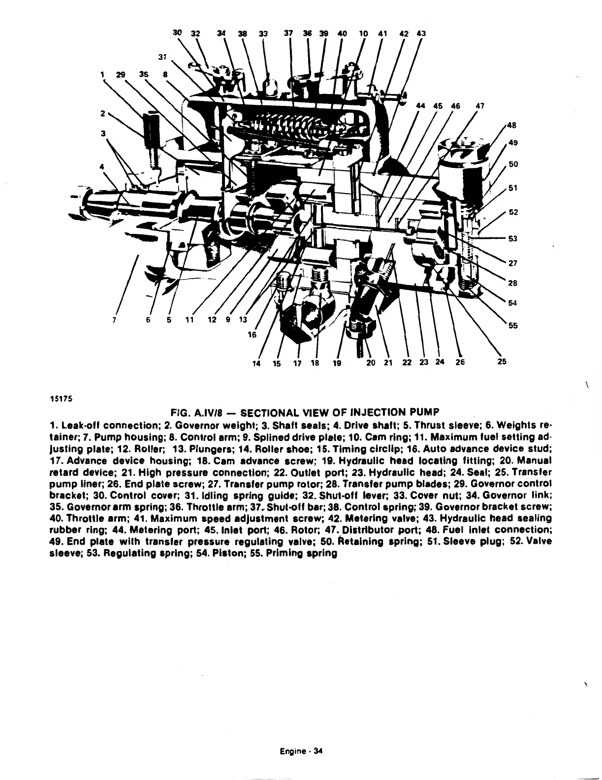
FIG. A.IV/8 - SECTIONAL VIEW OF INJECTION PUMP
1. Leak-off connection;
2.
Governor weight;
3.
Shaft seals;
4.
Drive shaft;
5.
Thrust sleeve;
6.
Weights re·
tainer;
7.
Pump housing;
8.
Control arm;
9.
Splined drive plate; 10. Cam ring; 11. Maximum fuel setting ad·
justing
plate; 12. Roller; 13. Plungers; 14. Roller shoe; 15. Timing
circlip;
16. Auto advance device stud;
17. Advance device housing; 18. Cam advance screw; 19. Hydraulic head locating
fitting;
20.
Manual
retard device;
21.
High pressure connection;
22.
Outlet port; 23. Hydraulic head;
24.
Seal;
25.
Transfer
pump
liner;
26.
End plate screw;
27.
Transfer pump rotor;
28.
Transfer
pump
blades;
29.
Governor control
bracket;
30.
Control cover;
31.
Idling spring guide;
32.
Shut-off lever;
33.
Cover nut;
34.
Governor link;
35.
Governor arm spring;
36.
Throttle arm;
37
r Shut-off bar;
38.
Control spring;
39.
Governor bracket screw;
40. Throttle arm;
41.
Maximum speed adjustment screw;
42.
Metering valve;
43.
Hydraulic head sealing
rubber ring; 44. Metering port; 45. Inlet port;
46.
Rotor; 47. Distributor port;
48.
Fuel Inlet connection;
49. End plate
with
transfer pressure regulating valve; 50. Retaining spring;
51.
Sleeve plug;
52.
Valve
sleeve;
53.
Regulating spring;
54.
Piston;
55.
Priming spring
Engine·
34
\
\
 Loading...

