55371
FIG. C.0/14 ASSEMBLY MARKS FOR CORRECT
INSTALLATION OF INTERNAL ARM AND LIFT
ARMS ON
THE
ROCKSHAFT
ASSEMBLY
The hydraulic
lift
is reassembled and refitted
to
the
tractor
by
reversing
the
sequence
of
opera·
tions
described
in the
preceding
chapters,
then
tighten
the
screws
and
nuts
to
torque
specifica-
tions.
Also,
consider
the
following
indications:
1.
Arrange
the
inside
arm and
lift
arms on
the
rockshaft
with
the
assembly
marks
aligned
(Fig. C.0/14).
A few
tractors
have
experienced
trouble
in
getting
a
mounted
plow
in
the
ground. When
this
happens, the
flat
load
measuring
spring
at
the
rear
of
the
lift
housing
compresses
completely
against
the
lift
housing.
The trac-
tion
booster
cannot
work.
Fig. C.0/1
shows
one
mark
on
the
rockshaft
and one
mark
on
the
internal arm, however,
the
Tractor
has
two
numbers
on
the
rockshaft, a
two
(2)
and a
four
(4). Some trac-
tors
have
the
mark
on
the
internal arm
lined
up
with
the
four
(4)
which
causes
the
tractor
booster
problem.
This
can be seen by remov-
ing
the
spring
and rear cover
from
the
lift
arm
housing.
This
can
also
be
corrected
by
changing
the
position
of
the
lift
arms
on
their
splines. The
stop
screw
on
the
full
raise
of
the
linkage
will
have
to
be readjusted.
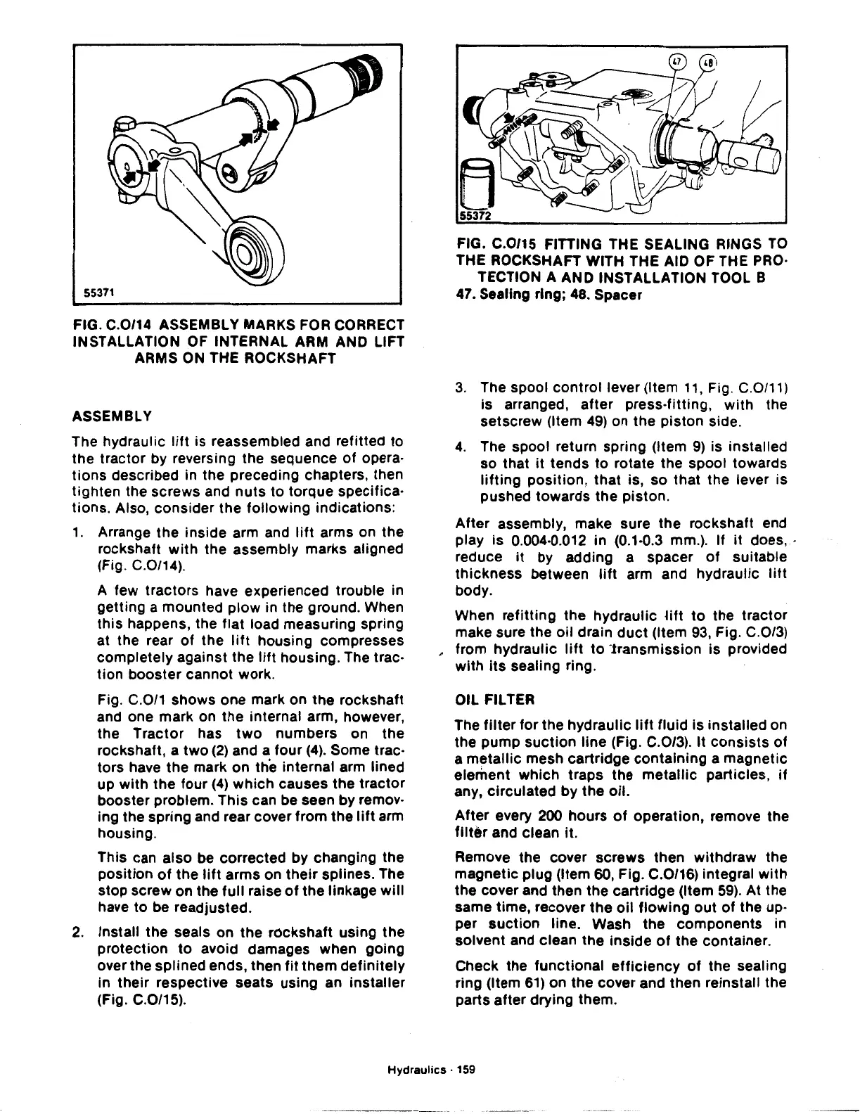
2.
Install
the
seals
on
the
rockshaft
using
the
protection
to
avoid damages when
going
over the
splined
ends,
then
fit
them
definitely
in
their
respective
seats
using
an
installer
(Fig. C.0/15).
FIG. C.0/15 FITTING THE SEALING RINGS TO
THE ROCKSHAFT WITH THE AID
OF
THE PRO·
TECTION A
AND
INSTALLATION TOOL B
47. Sealing
ring;
48. Spacer
3.
The spool
control
lever (Item
11,
Fig. C.0/11)
is arranged,
after
press-fitting,
with
the
setscrew
(Item 49) on
the
piston
side.
4.
The spool return
spring
(Item
9)
is
installed
so
that
it
tends
to
rotate
the
spool
towards
lifting
position,
that
is,
so
that
the
lever is
pushed
towards
the
piston.
After
assembly, make sure
the
rockshaft
end
play
is
0.004·0.012
in
(0.1·0.3 mm.).
If
it
does, ·
reduce
it
by
adding
a
spacer
of
suitable
thickness
between
lift
arm and
hydraulic
litt
body.
When
refitting
the
hydraulic
Hft
to
the
tractor
make sure
the
oil
drain
duct
(Item 93, Fig. C.0/3)
~
from
hydraulic
lift
to
'.transmission
is
provided
with
its
sealing ring.
OIL FILTER
The
filter
for
the
hydraulic
lift
fluid
is
installed
on
the
pump
suction
line
(Fig. C.0/3).
It
consists
of
a
metallic
mesh
cartridge
containing
a
magnetic
element
which
traps
the
metallic
particles,
if
any,
circulated
by
the
oil.
After
every 200
hours
of
operation,
remove
the
filter
and
clean
it.
Remove
the
cover
screws
then
withdraw
the
magnetic
plug
(Item 60, Fig. C.0/16) integral
with
the
cover and
then
the
cartridge
(Item 59).
At
the
same
time,
recover
the
oil
flowing
out
of
the
up·
per
suction
line. Wash
the
components
in
solvent
and clean
the
inside
of
the
container.
Check the
functional
efficiency
of
the
sealing
ring (Item 61) on
the
cover
and
then
reinstall
the
parts
after
drying
them.
Hydraulics · 159
 Loading...

