C.O HYDRAULIC LIFT AND POWER STEERING
54001
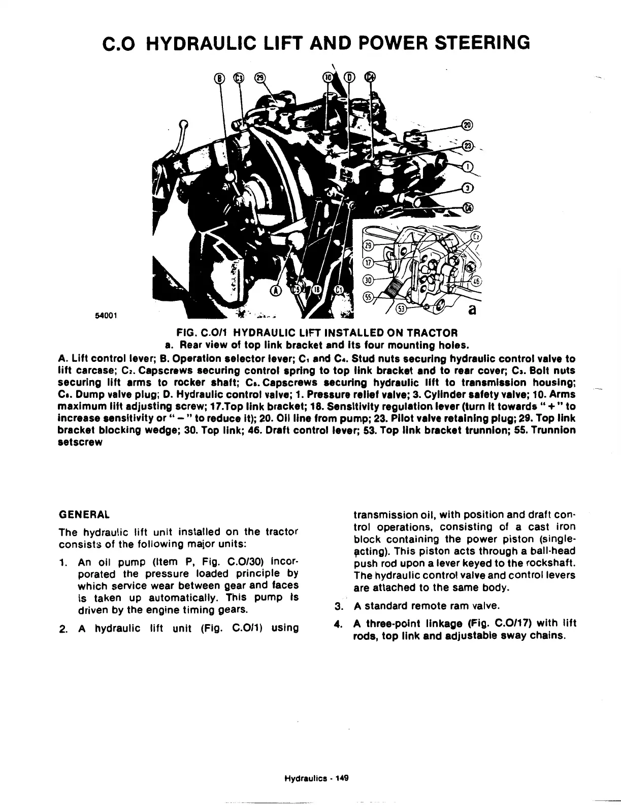
FIG. C.0/1 HYDRAULIC LIFT INSTALLED ON TRACTOR
a.
Rear view
of
top link bracket and
Its
four mounting holes.
A.
Lift control lever;
B.
Operation selector lever;
c,
and c
•.
Stud nuts securing hydraulic control valve
to
lift
carcase;
Ca.
Capscrews securing control spring
to
top
link
bracket and
to
rear cover; c,. Bolt
nuts
securing
lift
arms to rocker shaft;
Ca.
Capscrews securing hydraulic
lift
to
transmission housing;
c
•.
Dump valve plug;
D.
Hydraulic control valve;
1.
Pressure relief valve;
3.
Cylinder safety valve;
10.
Arms
maximum
lift
adjusting screw; 17.Top
link
bracket; 18. Sensitivity regulation lever (turn It
towards"+"
to
increase sensitivity
or"-"
to reduce It);
20.
Oil line from pump;
23.
Pilot valve retaining plug;
29.
Top
link
bracket blocking wedge;
30.
Top link; 46. Draft control lever;
53.
Top
link
bracket trunnion;
55.
Trunnion
setscrew
GENERAL
The hydraulic
lift
unit installed on the tractor
consists of the following major units:
1.
An
oil pump (Item
P,
Fig. C.0/30) incor-
porated the pressure loaded principle by
which service wear between gear and faces
is taken up automatically. This pump
ts
driven by the engine timing gears.
2.
A hydraulic
lift
unit
(Fig. C.0/1) using
transmission oil, with position and draft con-
trol operations, consisting
of
a cast iron
block containing the power piston (single-
,cting).
This piston acts through a ball-head
push rod upon a lever keyed to the rockshaft.
The hydraulic control valve and control levers
are attached
to
the same body.
3.
A standard remote ram valve.
4. A three-point linkage (Fig. C.0/17) with
lift
rods,
top
link
and adjustable sway chains.
Hydraulics • 149
 Loading...

