\
is
locked
by
the
stop (0, Fig. B.IX/14). Measure
dimension
X and
check
on the drive
pinion
the
permissible
error
A.
A CAUTION: Measure
dimension
X
only
after
ad·
justing
the
spring
A2,
so
that
the bear-
ings
support
rotation
is
made using a
torque
indicator
handle wrench.
The shim
thickness
for the drive
pinion
should
be:
S2
= (X • A) in. (mm.).
Remove the plate and the drive
pinion
support
from
the device, the inner races
of
the bevel sup·
ports
and the drive pinion support.
To
reassembly the bevel pinion support
with
the
bevel pinion, insert on the bevel
pinion
a shim
and then press on the bevel
pinion
shaft the in·
ner race
of
the roller bearing (Item
51,
Fig.
B.IX/12).
1.
Introduce the bushings
(50)
the
shims
(16)
for
the drive
pinion
bearings and finally the bevel
pinion
support
(43).
2.
Press the bearing inner race
(51)
on the bevel
pinion.
3.
Fit on the support the oil ring
(48)
after
inser-
ting
the spring. Prior
to
pressing the sealing
will
be coated
with
lithium
base lubricant
grease in the spring location and on the seal·
ing lug.
4.
Fit the bevel pinion support cover
(59)
on the
pinions
support by
fully
tightening
the 3
screws and securing by circlips.
5.
Insert the splined flange
(47)
on the shaft,
then the washer
(46)
and
tighten
the splined
D
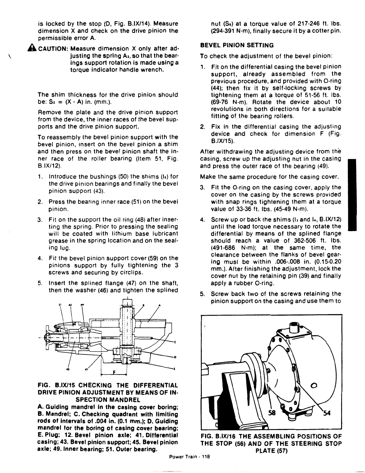
FIG. B.IX/15 CHECKING THE DIFFERENTIAL
DRIVE PINION ADJUSTMENT
BY
MEANS OF IN·
SPECTION MANDREL
A.
Guiding
mandrel In the casing cover boring;
B. Mandrel; C. Checking quadrant
with
limiting
rods
of
intervals
of
.004 in.
(0.1
mm.);
D.
Guiding
mandrel
for
the
boring
of
casing cover bearing;
E.
Plug; 12. Bevel
pinion
axle; 41. Differential
casing;
43.
Bevel
pinion
support; 45. Bevel
pinion
axle; 49.
Inner
bearing; 51. Outer bearing.
nut
(Se)
at a torque value
of
217·246 ft. lbs.
(294-391 N-m),
finally
secure
it
by a
cotter
pin.
BEVEL PINION SETTING
To
check
the
adjustment
of
the bevel pinion:
1.
Fit
on the
differential
casing the bevel
pinion
support,
already
assembled
from
the
previous procedure, and provided
with
0-ring
(44);
then
fix
it
by
self-locking
screws by
tightening
them at a torque
of
51-56 ft. lbs.
(69-76 N-m). Rotate the device about
10
revolutions
in both
directions
for
a suitable
fitting
of
the bearing rollers.
2.
Fix in
the
differential
casing the
adjusting
device and
check
for
dimension
F (Fig.
B.IX/15).
After
withdrawing
the
adjusting
device from the
casing, screw up the
adjusting
nut
in the casing
and press the outer race
of
the bearing
(49).
Make the same procedure
for
the casing cover.
3.
Fit the
0-ring
on the casing cover, apply the
cover on the casing by the
screws
provided
with
snap rings
tightening
them
at a torque
value
of
33-36 ft. lbs. (45-49 N-m).
4.
Screw up or back the
shims
(13
and
1.,
B.IX/12)
until
the load torque necessary
to
rotate the
differential
by means
of
the splined flange
should
reach a value
of
362-506 ft. lbs.
(491-686 N-m); at
the
same
time,
the
clearance between the flanks
of
bevel gear-
ing
must
be
within
.006·.008 in. (0.15·0.20
mm.).
After
finishing
the adjustment,
lock
the
cover
nut
by the retaining pin
(39)
and finally
apply a rubber
0-ring.
5.
Screw
back
two
of
the screws retaining
the
pinion
support
on the casing and use them
to
FIG. B.IX/16 THE ASSEMBLING POSITIONS OF
THE STOP (56) AND
OF
THE STEERING STOP
PLATE (57)
Power
Train·
118
 Loading...

