55382
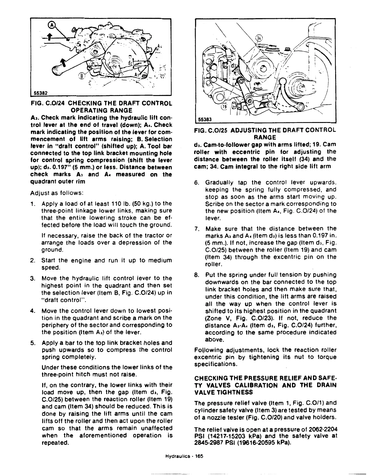
FIG. C.0/24 CHECKING THE DRAFT CONTROL
OPERATING RANGE
A,. Check mark
indicating
the hydraulic
lift
con·
trol
lever at
the
end
of
travel (down); A
•.
Check
mark
indicating
the
position
of
the lever for com·
mencement
of
lift
arms raising; B. Selection
lever in
"draft
control"
(shifted up);
A.
Tool bar
connected
to
the
top
link
bracket
mounting
hole
for
control spring compression
(shift
the lever
up);
da.
0.197"
(5
mm.)
or
less. Distance between
check
marks
A3
and A. measured
on
the
quadrant
outer
rim
Adjust
as
follows:
1.
Apply a load
of
at least
110
lb.
(50
kg.) to the
three-point linkage lower links, making sure
that the entire lowering stroke can be ef·
fected before the load
will
touch
the ground.
If necessary, raise the back
of
the
tractor
or
arrange
the
loads over a depression
of
the
ground.
2.
Start the engine and run
it
up
to
medium
speed.
3.
Move
the
hydraulic
lift
control
lever
to
the
highest
point
in the quadrant and then set
the selection lever (Item
B,
Fig. C.0/24) up in
"draft
control".
4. Move the
control
lever down
to
lowest posi·
tion in the quadrant and scribe a mark on the
periphery
of
the
sector
and corresponding
to
the
position
(Item A,)
of
the lever.
5.
Apply a bar
to
the
top
link
bracket holes and
push upwards so
to
compress the
control
spring completely.
Under these
conditions
the
lower
links
of
the
three-point
hitch
must
not
raise.
If, on
the
contrary,
the
lower
links
with
their
load move up, then
the
gap (Item d,, Fig.
C.0/25) between the reaction roller (Item
19)
and cam (Item
34)
should
be
reduced. This is
done by raising
the
lift
arms
until
the cam
lifts
off
the roller and then act upon the roller
cam so
that
the arms remain unaffected
when
the
aforementioned
operation
is
repeated.
55383
FIG. C.0/25 ADJUSTING THE DRAFT CONTROL
RANGE
d,.
Cam-to-follower gap
with
arms
lifted;
19. Cam
roller
with
eccentric
pin
for
adjusting
the
distance
between
the
roller
itself
(34)
and the
cam; 34. Cam integral to the right side
lift
arm
6.
Gradually tap
the
control lever upwards.
keeping the spring
fully
compressed, and
stop
as soon
as
the arms start moving up.
Scribe on the
sector
a mark corresponding to
the new
position
(Item A., Fig. C.0/24)
of
the
lever.
7.
Make sure that the
distance
between the
marks A, and A. (Item
da)
is less than 0.197 in.
(5
mm.). If not, increase
the
gap (Item
dl,
Fig.
C.0/25) between the roller (Item
19)
and cam
(Item
34)
through the
excentric
pin
on
the
roller.
8.
Put
the
spring under full tension by
pushing
downwards on
the
bar connected
to
the
top
link
bracket
holes
and then make sure that,
under
this
condition,
the
lift
arms are raised
all the way up when the
control
lever is
shifted
to
its
highest
position
in
the
quadrant
(Zone
V,
Fig. C.0/23).
If
not, reduce
the
distance
A,-A. (Item
da,
Fig. C.0/24) further,
according
to
the
same procedure
indicated
above.
Following
adjustments,
lock
the
reaction roller
excentric
pin by
tightening
its
nut
to
torque
specifications.
CHECKING THE PRESSURE RELIEF AND SAFE-
TY VALVES CALIBRATION AND THE DRAIN
VALVE TIGHTNESS
The pressure relief valve (Item
1,
Fig. C.0/1) and
cylinder
safety valve (Item
3)
are tested by means
of
a nozzle
tester
(Fig. C.0/20) and valve holders.
The relief valve
is
open at a pressure
of
2062-2204
PSI (14217-15203 kPa) and
the
safety valve at
2845-2987
PSI
(19616-20595 kPa).
Hydraulics
· 165
 Loading...

