FIG. 8.1/4 REMOVING (REPLACING) THE
10"
CLUTCH FROM THE ENGINE FLYWHEEL
US·
lNG THE ALIGNMENT PILOT
c
•.
Clutch
to
flywheel
attaching
capscrews;
2.
P.T.O.
clutch
release lever rod;
C2.
Capscrews;
E.
Clutch
centering
shaft
7.
Remove all
attaching
capscrews (Items Cl
and
c~.
Fig. 8.1/6) and move the engine front
axle unit forward. separating it from the
transmission
housing
and then placing it on
a shop stand (Fig.
8.1/4)
after
suitably wedg·
ing the front wheels.
8.
Remove the
clutch
unit from the engine
flywheel. as follows:
Remove. in alternate order. four
of
the six at·
taching cap screws (Item
c
..
Fig. 8.1/4) and
loosen the remaining
two
screws.
Introduce
the
clutch
alignment
pilot
(Item
E.
Fig. 8.1/4) inside the
clutch
shaft locations.
Withdraw the remaining
two
screws and
remove
the
complete
unit and the three rods
(Item
2) from
their
flywheel locations.
10"
CLUTCH DISASSEMBLY
Prior
to
disassembly, mark the
following
items:
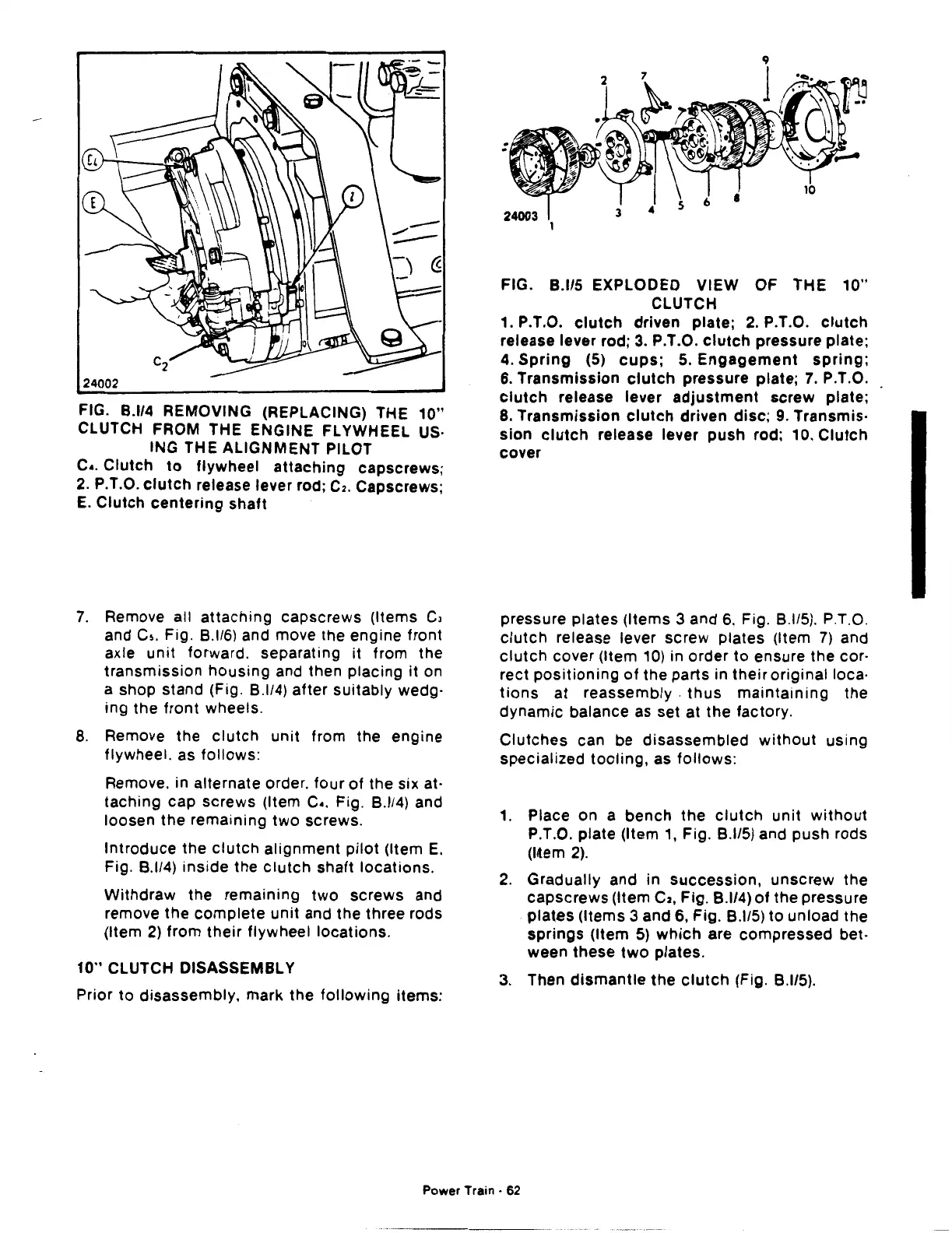
FIG.
8.115
EXPLODED VIEW OF THE
10"
CLUTCH
1. P.T.O.
clutch
driven plate; 2. P.T.O.
clutch
release lever rod; 3. P.T.O.
clutch
pressure plate;
4.
Spring
(5)
cups;
5.
Engagement
spring;
6.
Transmission
clutch
pressure plate;
7.
P.T.O.
clutch
release lever
adjustment
screw plate;
8. Transmission
clutch
driven
disc;
9. Transmis·
sion
clutch
release lever push rod; 10.
Clutch
cover
pressure plates (Items
3 and
6.
Fig. 8.1/5). P.T.O.
clutch
release lever screw plates (Item 7) and
clutch
cover (Item 10) in order
to
ensure the cor·
rect
positioning
of
the parts in
their
originalloca·
tions
at reassembly .
thus
maintaining
the
dynamic
balance as set at the factory.
Clutches
can be disassembled
without
using
specialized
tooling,
as
follows:
1. Place on a
bench
the
clutch
unit
without
P.T.O. plate (Item 1, Fig.
8.115)
and push rods
(14em
2).
2.
Gradually and in
succession,
unscrew the
capscrews
(Item
C2,
Fig. 8.1/4)
of
the pressure
plates
(Items 3 and 6, Fig.
8.115)
to
unload the
springs
(Item
5)
which
are compressed bet·
ween these
two
plates.
3.
Then
dismantle
the
clutch
(Fig.
8.115).
Power Train · 62
 Loading...

