15161
FIG.
A.IV/2
CROSS-SECTION
OF
FUEL
TRANSFER PUMP
c
..
Self-locking screws
attaching
shaft
(1)
to
gear
(2);
1. Fuel
lift
pump
drive gear;
2.
Eccentric drive
shafts
FUEL TANK
Clean the fuel tank thoroughly at engine
overhauls. From
time
to time, drain water con-
densation and
deposits
by removing the
bottom
plug. Be sure the tank is
almost
empty
when
draining it, and repeat more often in wet,
cold
or
unstable climates. See that the vent hole on the
fuel
filler
cap is open.
FUEL PRIMING PUMP
The
double
diaphragm fuel priming
pump
is ac-
tuated by a cam
which
is driven by the
injection
pump
drive
intermediate
gear (Fig. A.IV/2) and in-
corporates one fuel intake and one
outlet
valve.
At
pump
overhaul see that the
two
valves and the
screen
filter
(Item
4,
Fig. A.IV/3) are clean and the
diaphragm
(Item
10)
unbroken.
At
pump
disassembly
make the
double
diaphragm axle
rotate
1/4
turn
either
in
a
clockwise
or
counterclockwise
direction
to
disengage
the
control
lever (Item
8).
Fuel
priming
pump
specifications:
Minimum
Output
..................
31.7 gal/hr.
(120 liters/hr.)
Static
Delivery Pressure
............
7.115 P.S.I.
(49.05 KPa)
Speed
of
Cylindrical Driving Pin
(22
mm. dia. and 3 mm.
excentricity)
......................
1500
RPM
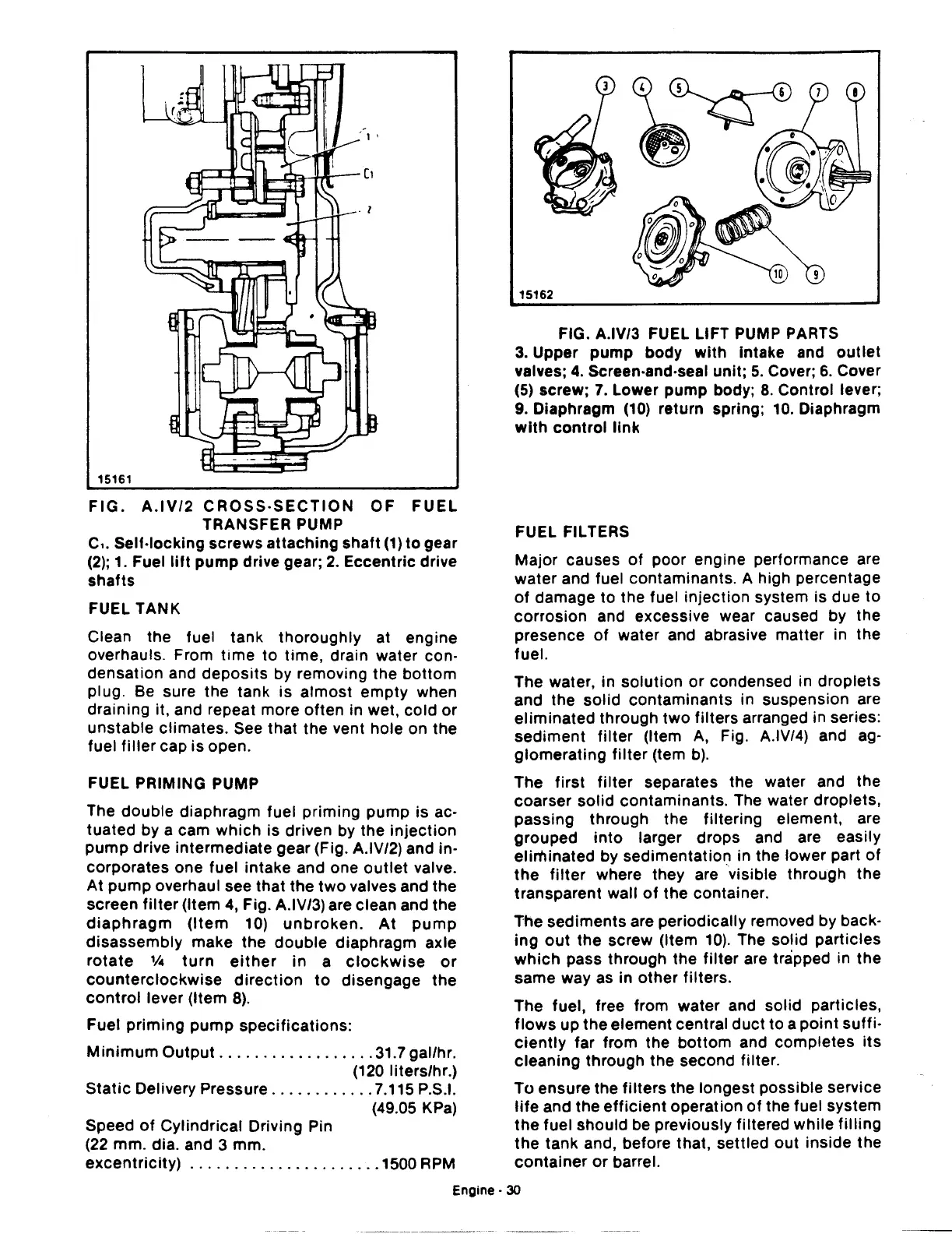
15162
FIG. A.IV/3 FUEL LIFT PUMP PARTS
3.
Upper
pump
body
with
intake and
outlet
valves;
4.
Screen-and-seal unit;
5.
Cover;
6.
Cover
(5)
screw;
7.
Lower pump body;
8.
Control lever;
9.
Diaphragm
(10)
return spring;
10.
Diaphragm
with
control
link
FUEL FILTERS
Major causes
of
poor engine performance are
water and fuel contaminants. A high percentage
of
damage to the fuel injection system is due
to
corrosion and excessive wear caused by the
presence
of
water and abrasive matter in the
fuel.
The water, in
solution
or condensed in
droplets
and
the
solid
contaminants in suspension are
eliminated
through
two
filters arranged in series:
sediment
filter
(Item
A,
Fig. A.IV/4) and ag-
glomerating
filter
(tem
b).
The first
filter
separates the water and the
coarser solid contaminants. The water droplets,
passing through the filtering element, are
grouped
into
larger drops and are easily
eliminated
by sedimentation in the lower part
of
the
filter
where they are visible through the
transparent wall
of
the
container.
The sediments are periodically removed by back·
ing
out
the
screw (Item
10).
The solid particles
which
pass through the
filter
are trapped in
the
same way as in
other
filters.
The fuel, free from water and solid particles,
flows
up
the
element central
duct
to
a
point
suffi·
ciently
far from the
bottom
and completes
its
cleaning through the second filter.
To ensure the
filters
the longest possible service
life
and the
efficient
operation
of
the fuel system
the
fuel should be previously filtered while
filling
the
tank and, before that, settled
out
inside
the
container
or
barrel.
Engine·
30
 Loading...

