In order
to
remove the double-type gear (Item
44,
Fig. B.IX/21)
it
is
absolutely
necessary
to
separate the gearbox-clutch
casing
from the
rear axle housing.
After
this
you
must
screw
back the screw
~9),
the plate and the in-
termediate shaft
(43)
recovering the
bushing
(48)
the washers
(29)
and
the
complete
gear.
3.
Then remove the bearing needles
(46),
the
bushing
(26),
after
withdrawing
the
circlips.
INSPECTION
Check the
dismantled
parts
according
to
the
remarks and technical data
comprised
in
this
chapter.
Check
if
the teeth are
not
worn
off
having in view
in special the teeth
chamfering
of
the
control
pi-
nion.
Check the clearance between the driven gear
grooves
(4)
and those
of
the splined shaft (Item
5,
B.IX/20).
Check the ball bearings
(12
and
14)
and the nee-
dle bearing (Item
45,
Fig. B.IX/21) are freely rotate
without
jamming; make sure they are
not
ex-
cessively worn off.
Make sure the
coupling
fork (7)
is
not
damaged
and worn
off.
No scratches are permitted.
Replace the oil ring (10 and
20)
if
it
is
damaged.
Check
for
the
elasticity
of
the
coil
spring
(23).
ASSEMBLING THE FRONT DRIVE AXLE SIDE
REDUCTION GEAR
When re-assembling
the
driving gear (Item
44,
Fig. B.IX/21) use the reverse procedure as
for
removal having in view the
following:
1.
the
bushing
(48)
and the
shaft
groove
(43)
must
be
fitted
so
that
to
permit
the P.T.O.
gear rotation, as
indicated
on Fig. B.IX/21.
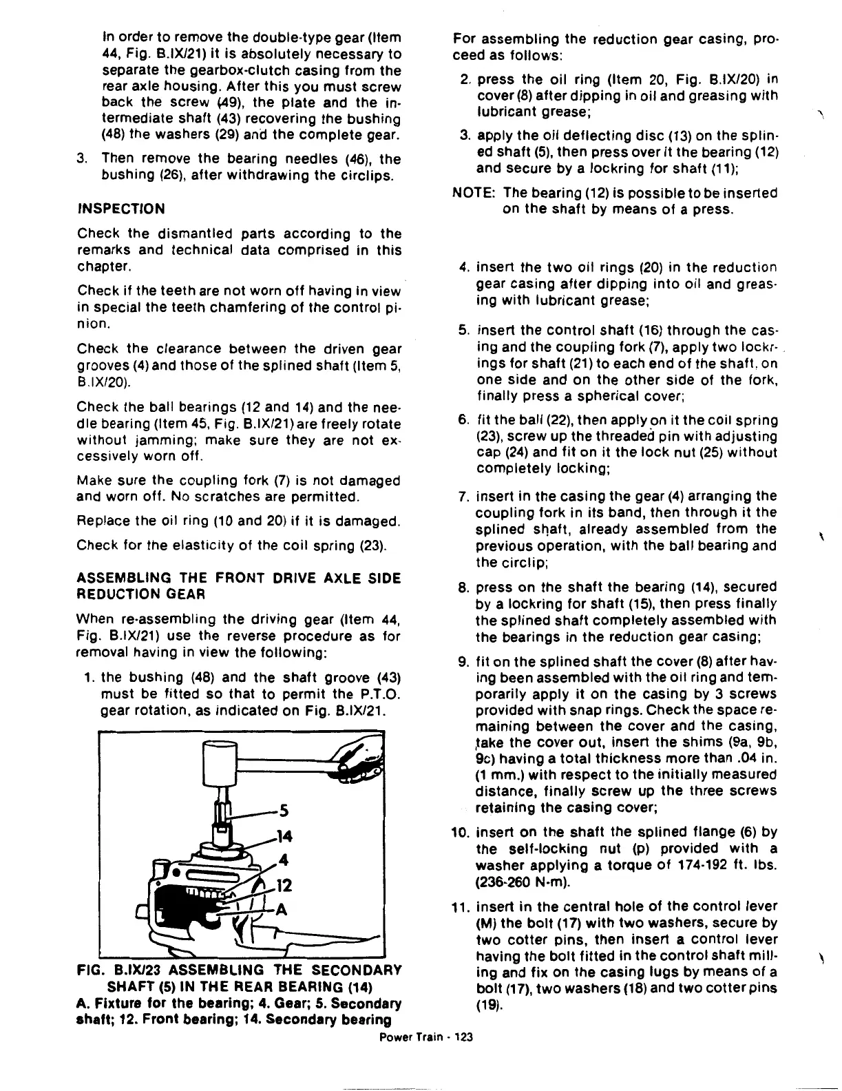
FIG. B.IX/23 ASSEMBLING THE SECONDARY
SHAFT
(5)
IN
THE REAR BEARING (14)
A. Fixture
for
the
bearing; 4. Gear; 5. Secondary
shaft;
12.
Front
bearing; 14. Secondary bearing
For
assembling
the
reduction
gear casing, pro-
ceed as
follows:
2.
press
the
oil
ring (Item 20, Fig. B.IX/20) in
cover
(8)
after
dipping
in
oil
and greasing
with
lubricant
grease;
3.
apply
the
oil
deflecting
disc
(13)
on the splin-
ed shaft
(5),
then
press over
it
the bearing
(12)
and secure by a
lockring
for
shaft
(11
);
NOTE: The bearing
(12)
is
possible
to
be inserted
on
the
shaft
by means
of
a press.
4.
insert
the
two
oil
rings
(20)
in the
reduction
gear
casing
after
dipping
into
oil
and greas-
ing
with
lubricant
grease;
5.
insert
the
control
shaft
(16)
through
the cas-
ing and the
coupling
fork
(7),
apply
two
lockr· .
ings
for
shaft
(21)
to
each end
of
the shaft, on
one side and on the
other
side
of the fork,
finally
press a spherical cover;
6.
fit
the ball
(22),
then
apply on
it
the
coil
spring
(23),
screw up the threaded pin
with
adjusting
cap
(24)
and
fit
on
it
the
lock
nut
(25)
without
completely
locking;
7.
insert
in
the
casing
the gear
(4)
arranging the
coupling
fork
in
its
band,
then
through
it
the
splined
st"Jaft,
already assembled
from
the
previous operation,
with
the ball bearing and
the
circlip;
8.
press
on
the
shaft
the bearing
(14),
secured
by a
lockring
for
shaft
(15),
then
press
finally
the
splined
shaft
completely
assembled
with
the
bearings in
the
reduction
gear casing;
9.
fit
on
the
splined
shaft
the cover
(8)
after
hav-
ing been
assembled
with
the
oil
ring and tem-
porarily apply
it
on
the
casing
by 3
screws
provided
with
snap rings.
Check
the space
re-
maining
between
the
cover and the casing,
,take
the
cover
out,
insert
the
shims
(9a, 9b,
9c) having a
total
thickness
more
than .04 in.
(1
mm.)
with
respect
to
the
initially
measured
distance,
finally
screw
up
the
three
screws
retaining
the
casing
cover;
10.
insert
on
the
shaft
the
splined
flange
(6)
by
the
self-locking
nut
(p) provided
with
a
washer
applying
a
torque
of
174-192 ft. lbs.
(236-260 N·m).
11. insert
in
the
central
hole
of
the
control
lever
(M)
the
bolt
(17)
with
two
washers, secure by
two
cotter
pins,
then
insert
a
control
lever
having
the
bolt
fitted
in
the
control
shaft
mill-
ing and
fix
on
the
casing
lugs
by means
of
a
bolt
(17),
two
washers
(18)
and
two
cotter
pins
(19).
Power
Train·
123
'

 Loading...
