Specifications:
Fluid
type
...........•...............•.........•.............
Exxon Torque Fluid
56
or
Equivalent
Fluid
capacity
of
transmission case
with
level reaching the upper
dipstick
mark
........
17
Qts. (161itres)
Available fluid for remote ram control
...........................................
10.6 Qts.
(10
lit
res)
Plessey gear type hydraulic pump
...................................................
Model
PO
10
Borg Warner gear type hydraulic pump
..................................................
Optional
Engine/pump speed ratio
................................................................
1:0.91
Pump speed (with engine running at 2400 RPM)
.........................................
2180
RPM
Corresponding
output
with
an
oil temperature
of
122• • 140•F.
(so•-so•c.)
and
2133
PSI
(14707
kPa) pressure at 2400 engine
RPM
.......................
5.75
GPM
(21.81itres/min.)
(Optional)
10
GPM
(37.8
litres/min.)
Pressure relief valve
setting
.......................................
2062·2204
PSI
(14217-15203
kPa)
Single-acting ram:
Bore and stroke
....................................................
3.54 x 3.54 in.
(90
x
90
mm)
Capacity
.................................................................
34.8 cu. in.
(570
cc)
Cylinder Safety valve pressure
setting
............................
2845-2987
PSI
(19616·20595 kPa)
Nominal
lifting
capacity
................................................
6075 ft.-lb.
(8236
N •
m)
Three-point linkage:
Maximum liftable weight at implement
mounting
points
with
lift
rods
connected
to
lower links
as
follows:
(Figure
17)
in holes
(a)
.....................................................
2645
lb. (1200 kg)
(Figure
17)
in holes
(b)
.....................................................
22051b. (1000 kg)
Lift
arms range
with
lift
rods connected
to
lower links as follows:
(Figure
17)
in holes
(a)
.....................................................
21.6 in.
(550
mm)
(Figure
17)
in holes
(b)
.....................................................
27.2
in.
(690
mm)
Lifting
time
with engine running at 2550
RPM
.............................................
1.5
sec.
Total weight
of
the hydraulic
lift
and linkage
........................................
2291b.
(104
kg)
55361
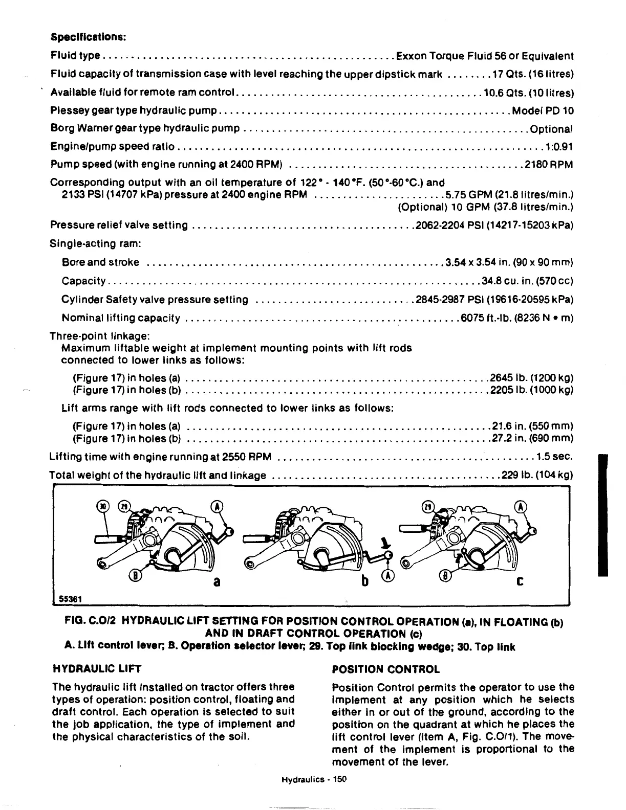
FIG. C.0/2 HYDRAULIC LIFT SETTING FOR POSITION CONTROL OPERATION
(a),
IN FLOATING (b)
AND IN DRAFT CONTROL OPERATION (c)
A.
Lift control lever; B. Operation
selector
lever;
29.
Top
link
blocking
wedge; 30. Top
link
HYDRAULIC LIFT
The hydraulic
lift
installed on tractor offers three
types
of
operation: position control, floating and
draft
control. Each operation is selected
to
suit
the
job
application, the type
of
implement and
the physical characteristics
of
the soil.
POSITION CONTROL
Position Control permits the operator
to
use the
Implement at any position which he selects
either
In
or
out
of
the ground, according
to
the
positron on the quadrant
at
which he places the
lift
control lever (Item
A,
Fig. C.0/1). The move-
ment
of
the Implement is proportional
to
the
movement
of
the lever.
Hydraulics·
150
 Loading...

