FIG. B.l/14 RIGHT-SIDE VIEW
OF
TRACTOR
WITHOUT REAR HOOD AND FUEL TANK
C3.
Upper
screws
securing
the
clutch·
transmission
housing
to
the engine crankcase;
C1.
and
Ca.
Tank
supports
front and rear at·
taching
capscrews; Fe. Electric cable strap;
18. Fuel tank
supports
the dashboard,
disconnecting
the trac-
tormeter
cable, electrical
connections
and
starting
switch
unit;
the fuel tank after
closing
the cocks, discon-
necting
the fuel level
indicator
wires and fuel
lines and removing the
mounting
brackets;
3.
Disconnect
the
electric
cables from the
engine starting safety push-button and from
the
rear
lighting
connections
and place the
cable strap assembly on the
engine
(Fe, Fig.
8.1114).
4.
Remove the fuel tank
supports
(18)
by
separating them from the central panel,
disconnecting
the
throttle
controls
from the
linkage and unserving the engine
stop
con-
trol
knob.
5.
Drain the
transmission
and rear
housings
of
lubricating
oil
and detach:
hydraulic
lift
oil
lines
from the pump install-
ed on
the
engine;
the
drag
link
from the steering box arm.
6. Put on
the
hand brake, insert
two
wooden
wedge
blocks
between the
front
axle and
its
support,
attach a
lifting
chain
to
the
transmission
housing
and
to
a
shop
hoist,
then
take
the
weight
off
and place a hydraulic
jack
under
the
engine
oil
sump.
7.
Remove all
attaching
capscrews
(C3
and
Cs,
Fig.
8.1117)
and move the engine-front axle
2
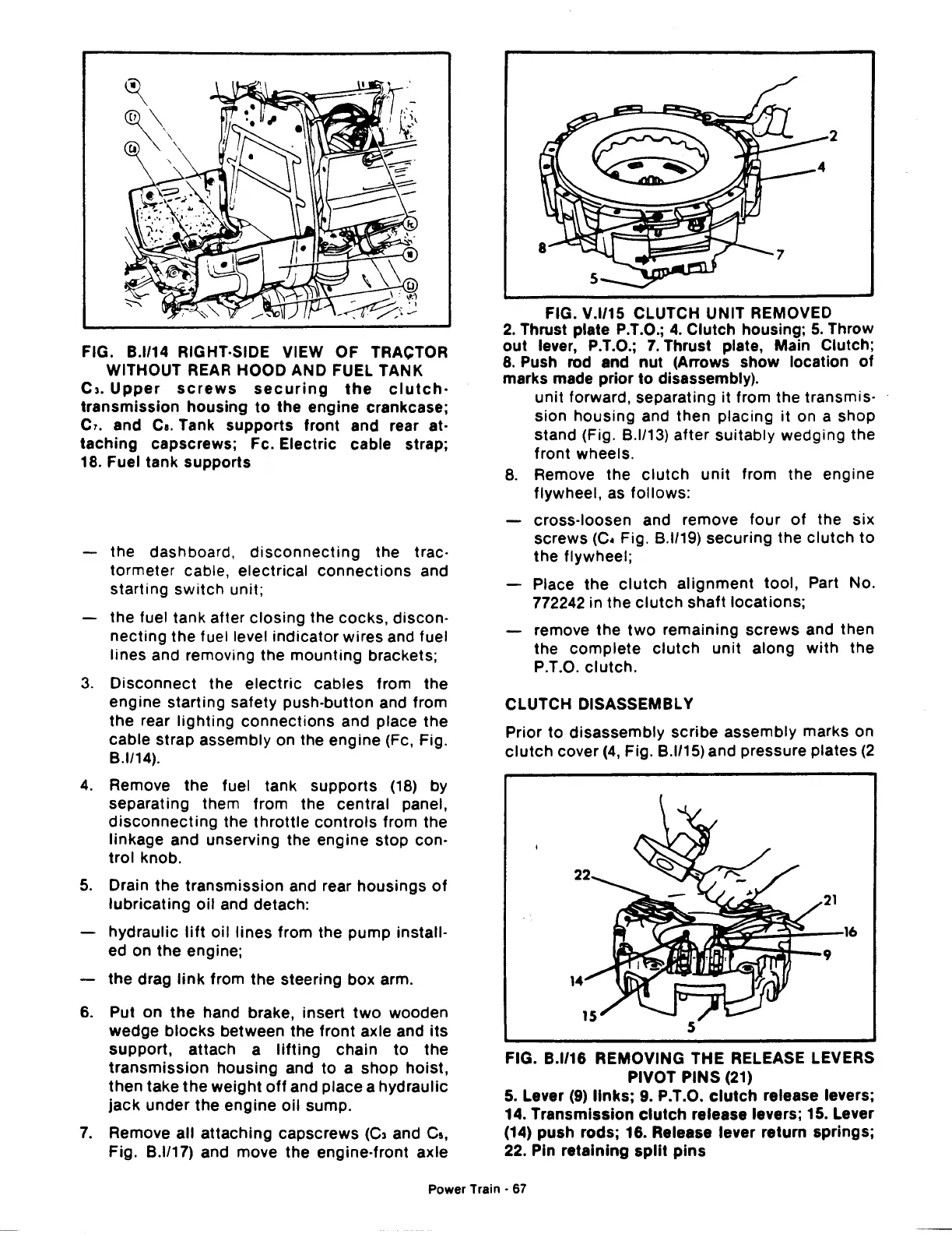
FIG. V.l/15 CLUTCH UNIT REMOVED
2 Thrust plate P.T.O.;
4.
Clutch housing;
5.
Throw
o~t
lever, P.T.O.;
7.
Thrust plate, Main
~lutch;
8.
Push rod and
nut
(Arrows show locat1on
of
marks made prior
to
disassembly). .
unit
forward, separating it from the transmis-
sion
housing
and then placing
it
on a shop
stand (Fig.
8.1113)
after
suitably
wedging
the
front
wheels.
8.
Remove the
clutch
unit
from the engine
flywheel, as
follows:
cross-loosen and remove four
of
the
six
screws
(C• Fig.
8.1119)
securing the
clutch
to
the
flywheel;
Place
the
clutch
alignment
tool,
Part No.
772242 in
the
clutch
shaft
locations;
remove
the
two
remaining
screws
and then
the
complete
clutch
unit
along
with
the
P.T.O.
clutch.
CLUTCH DISASSEMBLY
Prior
to
disassembly
scribe
assembly marks on
clutch
cover
(4,
Fig.
8.1115)
and pressure plates
(2
FIG. B.l/16 REMOVING THE RELEASE LEVERS
PIVOT PINS (21)
5.
Lever
(9)
links;
9. P.T.O.
clutch
release levers;
14.
Transmission
clutch
release levers; 15. Lever
(14) push rods; 16. Release lever return springs;
22. Pin
retaining
split
pins
Power
Train·
67
 Loading...

