DIFFERENTIAL REASSEMBLY
PINION SUPPORT
1.
Press bearing cone (Item
15,
Fig. B.X/12) on
to
pinion
shaft (Item
14),
tapered side out,
and seat
tightly
against
pinion
shoulder.
2.
Place spacer (Item
3)
and shim (Item
12)
onto
pinion shaft next
to
bearing inner race. The
spacer and shim
control
bearing adjustment.
3.
Press inner bearing cup
into
pinion
support
(Item
13),
taper outward. Invert support and
locate outer bearing cup (taper outward)
against inner shoulder. Install outer bearing
cone (Item
5),
new lip seal,
lip
in, (Item
11)
and
dust
cover (Item
10).
4.
Insert bevel
pinion
shaft
into
pinion support.
Install flange (Item
7),
washer (Item
9)
and
nut
(Item
8).
Tighten the nut
to
181
ft.-lbs. (245.4
N-m) torque. Wind a cord
(5·6
turns) around
the drive sleeve and using a pull scale on the
cord, check the rolling torque
of
the
pinion
shaft. This torque must be 4.2
to
8.4 in.-lbs.
(0.47-0.95 N·m). The scale reading should be
3.96
to 7.93 lbs. (17.6·35.3
N).
Do
not
read
the
starting torque. If the scale reading is less
than the above figure, reduce the shim stack.
If higher, add shims.
FIG. B.X/11 DIFFERENTIAL SUPPORT REMOV·
ED
FROM AXLE HOUSING
Cu.
Ring
nut
safety tab screw;
Cu.
Cup
holding
screw; 8.
Adjustment
ring nut; 17. Ringnut safety
tab; 18. Bearing cup. (Arrows Indicate assemble
marks)
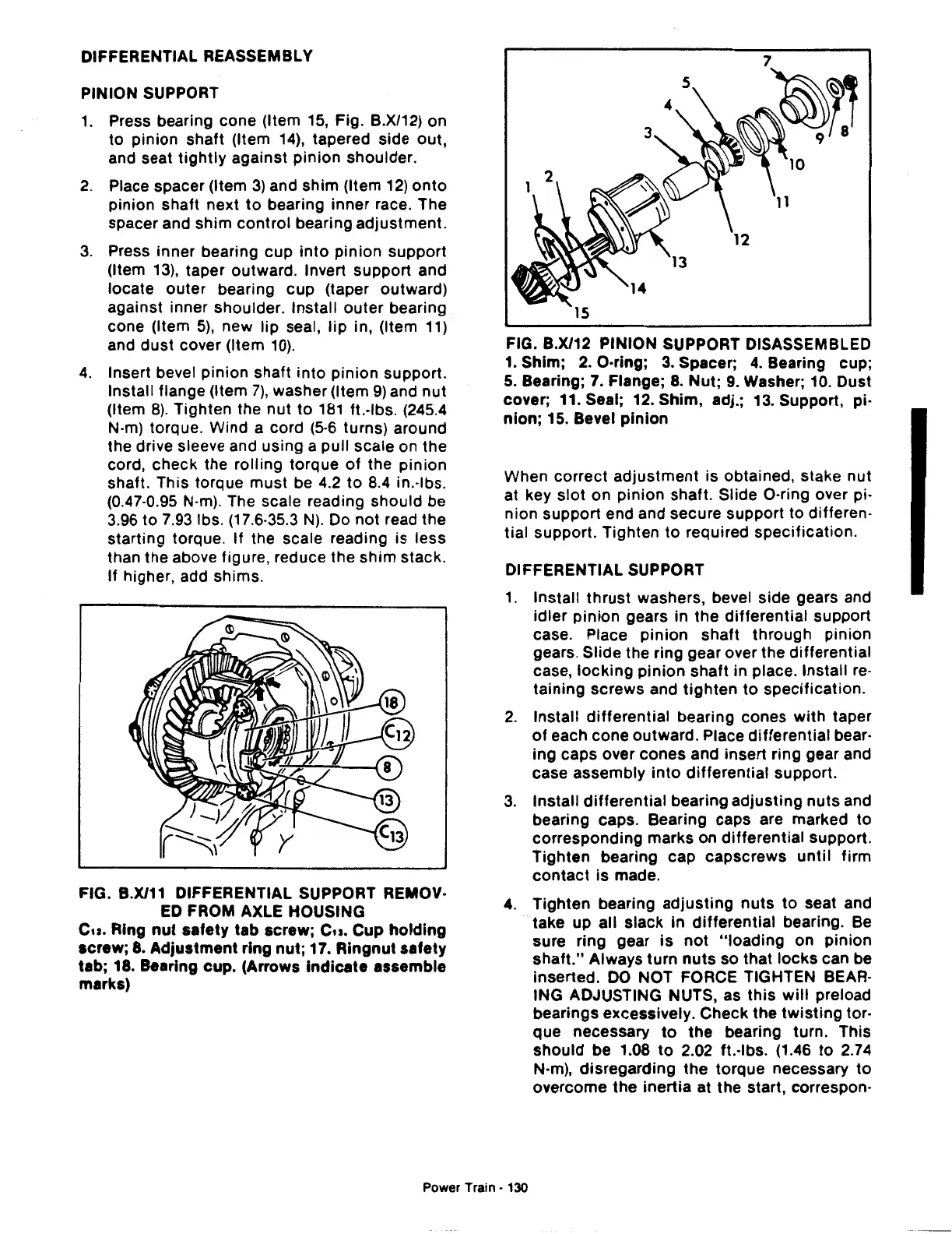
FIG. B.X/12 PINION SUPPORT DISASSEMBLED
1.
Shim;
2.
O·ring;
3.
Spacer;
4.
Bearing cup;
5.
Bearing;
7.
Flange;
8.
Nut;
9.
Washer;
10.
Oust
cover; 11. Seal; 12. Shim, adj.; 13. Support, pi·
nion;
15. Bevel
pinion
When correct
adjustment
is obtained, stake nut
at key
slot
on pinion shaft. Slide O·ring over pi·
nion support end and secure support to differen·
tial support. Tighten
to
required specification.
DIFFERENTIAL SUPPORT
1.
Install
thrust
washers, bevel side gears and
idler
pinion
gears in the differential support
case. Place
pinion
shaft through pinion
gears. Slide the ring gear over the differential
case,
locking
pinion
shaft in place. Install re·
taining screws and
tighten
to
specification.
2.
Install
differential
bearing cones
with
taper
of
each cone outward. Place differential bear·
ing caps over cones and insert ring gear and
case assembly
into
differential
support.
3.
Install
differential
bearing adjusting
nuts
and
bearing caps. Bearing caps are marked
to
corresponding marks on differential support.
Tighten bearing cap capscrews
until
firm
contact
is
made.
4.
Tighten bearing
adjusting
nuts
to
seat and
take up all slack in
differential
bearing. Be
sure ring gear
is
not
"loading
on
pinion
shaft."
Always turn
nuts
so that
locks
can be
inserted.
DO
NOT FORCE TIGHTEN BEAR·
lNG ADJUSTING NUTS, as
this
will
preload
bearings excessively. Check the
twisting
tor-
que necessary
to
the
bearing turn. This
should
be 1.08
to
2.02 ft.-lbs. (1.46
to
2.74
N·m), disregarding
the
torque necessary
to
overcome
the
inertia
at the start, correspon-
Power Train • 130
 Loading...

