1. SETTING THE CONTROL SPRING MOVE·
MENT
The correct
setting
of
the double
acting
control
spring (Item 94, Fig. C.0/19) ensures that the
valve spool
will
not
exceed the present
limits
and
that
the
complete
displacement, subdivided
into
compression
and tension,
is
the desired one. All
this
is
necessary
to
avoid mechanical troubles
such
as
spring
permanent yields
or
rupture or
leverage straining, etc.
Adjust
the
hydraulic
lift
installed on the
tractor
as follows:
1.
Remove the wedge (Item
29,
Fig. C.0/19) in-
serted
between
top
link
bracket
and
hydraulic
lift
rear cover.
2.
Check (with
control
lever free) that the
distance (Item L,) between top
link
upper
stop
and the rear cover
of
the hydraulic
lift
is
0.583-0.594 in. (14.8-15.1 mm.). If the distance
is less, add
shims
(Item
H)
between control
spring (Item
94)
and top
link
bracket (Item
17);
reduce them
if
more.
3.
Connect a lever
to
the
top
link
bracket holes
and push downwards
until
the spring has ef·
fected
its
full tension stroke. Make sure that
the distance (Item
l2)
between the upper top
link
bracket
stop
and rear cover
of
the
hydraulic
lift
is
comprised
between
0.748-0.787 in. (19-20 mm.). If it is more, cor-
rect it by
building
up the lower
stop
surface
through
electric
welding.
~------------~
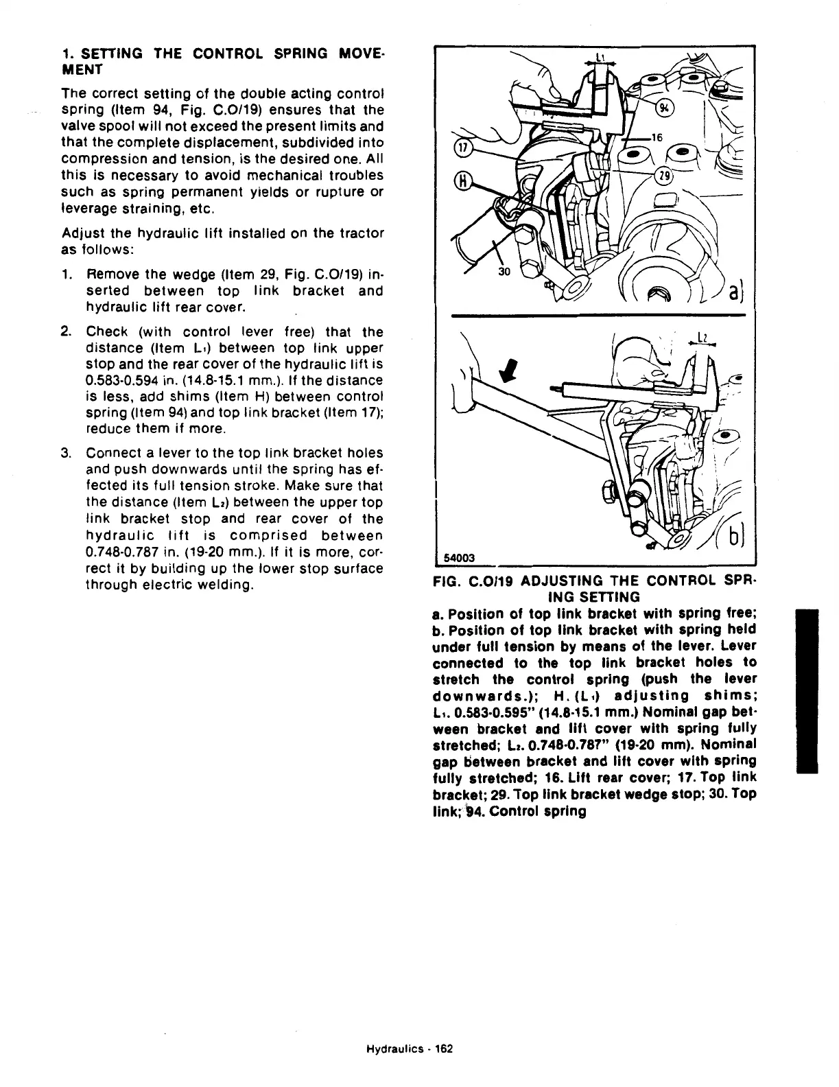
FIG. C.0/19 ADJUSTING THE CONTROL SPR·
lNG
SETTING
a.
Position
of
top
link
bracket
with
spring
free;
b.
Position
of
top
link
bracket
with
spring
held
under
full
tension
by means
of
the lever. Lever
connected
to
the
top
link
bracket
holes
to
stretch
the
control
spring
(push the lever
downwards.);
H.
(L,)
adjusting
shims;
L,. 0.583·0.595" (14.8·15.1 mm.)
Nominal
gap
bet-
ween bracket and
lift
cover
with
spring
fully
stretched;
Lz.
0.748·0.787" (19·20 mm).
Nominal
gap t)etween bracket and
lift
cover
with
spring
fully
stretched;
16.
Lift
rear cover; 17. Top
link
bracket; 29.
Top
link
bracket wedge stop; 30. Top
link;
94.
Control
spring
Hydraulics
· 162
 Loading...

