55388
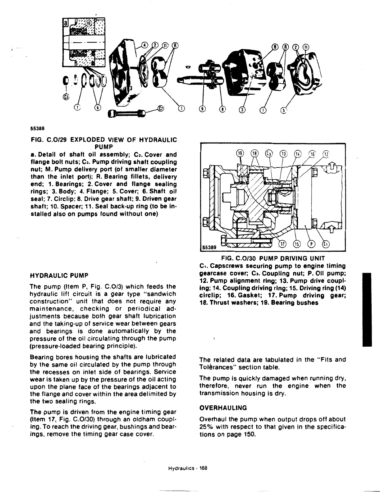
FIG. C.0/29 EXPLODED VIEW OF HYDRAULIC
PUMP
a. Detail
of
shaft
oil
assembly;
C2.
Cover and
flange bolt nuts;
CJ.
Pump driving
shaft
coupling
nut;
M. Pump delivery port (of smaller diameter
than the
inlet
port);
R.
Bearing
fillets,
delivery
end;
1.
Bearings;
2.
Cover and flange sealing
rings;
3.
Body;
4.
Flange;
5.
Cover;
6.
Shaft
oil
seal;
7.
Circlip;
8.
Drive gear shaft;
9.
Driven gear
shaft;
10.
Spacer;
11.
Seal back·up ring (to be in·
stalled also on pumps found
without
one)
HYDRAULIC PUMP
The pump (Item
P,
Fig. C.0/3) which feeds the
hydraulic
lift
circuit
is a gear type
"sandwich
construction"
unit that does not require any
maintenance,
checking
or
periodical
ad·
justments
because both gear shaft lubrication
and the taking-up
of
service wear between gears
and bearings is done
automatically
by the
pressure
of
the oil circulating through the pump
(pressure-loaded bearing principle).
Bearing bores housing the shafts are lubricated
by
the
same
oil
circulated by the pump through
the
recesses on inlet side
of
bearings. Service
wear is taken up by the pressure
of
the
oil
acting
upon the plane face
of
the bearings adjacent
to
the
flange and cover
within
the area
delimited
by
the
two
sealing rings.
The pump is driven from the engine
timing
gear
(Item
17,
Fig. C.0/30) through
an
oldham coupl·
ing. To reach the driving gear,
bushings
and bear·
ings, remove the
timing
gear case cover.
FIG. C.0/30 PUMP DRIVING UNIT
c,.
Capscrews securing
pump
to
engine
timing
gearcase cover; c,. Coupling nut;
P.
Oil pump;
12. Pump alignment ring; 13. Pump drive coupl·
ing; 14. Coupling driving ring; 15. Driving ring
(14)
circlip;
16. Gasket; 17.
Pump
driving
gear;
18. Thrust washers; 19. Bearing bushes
The related data are tabulated in the
"Fits
and
Tolerances" section table.
The pump is
quickly
damaged when running dry,
therefore, never run
the
engine when the
transmission housing is dry.
OVERHAULING
Overhaul the pump when
output
drops
off
about
25%
with
respect
to
that given in
the
specifica·
tions
on page 150.
Hydraulics
· 168
 Loading...

